ANTI-LOCK BRAKES
Anti-lock Brakes Wiring Diagram for Chevrolet Blazer 2005
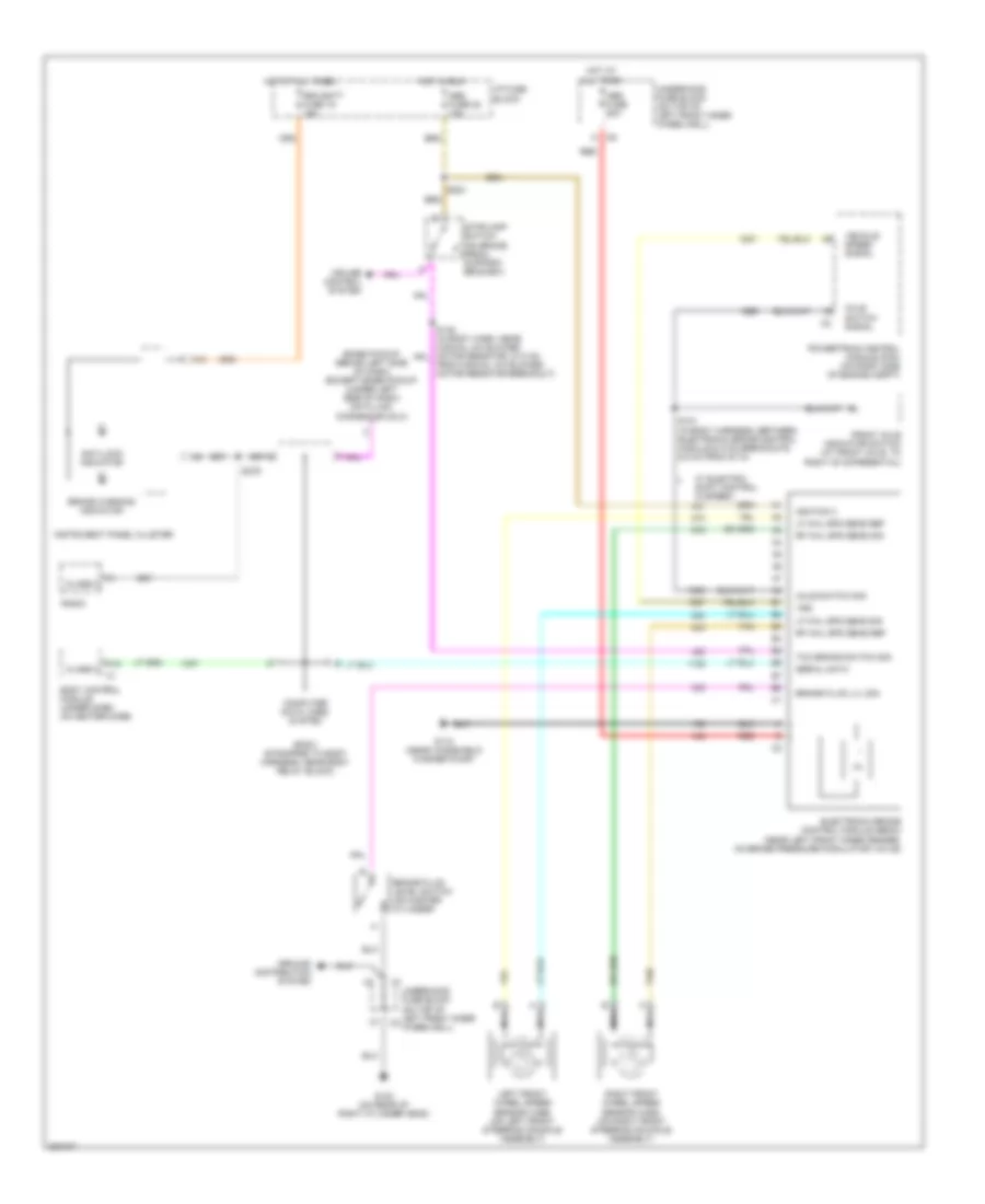
List of elements for Anti-lock Brakes Wiring Diagram for Chevrolet Blazer 2005:
- (base pickup: behind left side of dash) (except base pickup: (under left side of dash) data link connector (dlc)
- A10
- A12
- Abs fuse 22 10a
- Abs fuse 60a
- Anti-lock indicator
- Axle switch sig
- Axle switch signal
- Body control module (under dash, on heater case)
- Brake fluid level switch (on master cylinder)
- Brake fluid lvl sig
- Brake warning indicator
- Class 2
- Computer data lines system
- Cruise control system
- Electronic brake control module (ebcm) (near left front inner fender, on brake pressure modulator valve)
- From manual a/c blower motor resistor breakout)
- Front axle indicator switch (at front axle, to right of differential)
- G102 (on rear of right cylinder head)
- G110 (near windshield washer pump)
- Ground distribution system
- Hot at all times
- Hot in run
- I/p fuse block
- Ignition 3
- Instrument panel cluster
- Left front wheel speed sensor (wss) (on left front steering knuckle assembly)
- Lf whl spd sens ref
- Lf whl spd sens sig
- Nca
- Powertrain control module (pcm) (on right side of engine compt)
- Radio
- Rdo batt fuse 19 15a
- Red
- Rf whl spd sens ref
- Rf whl spd sens sig
- Right front wheel speed sensor (wss) (on right front steering knuckle assembly)
- S121 (in body harness, between electronic brake control module & c102 breakouts, 6.5 cm from s113)
- S203
- S276
- Serial data
- Sp201 (strapped to body harness, near body relay block)
- Stoplamp switch (on brake pedal support bracket)
- Tan
- Tcc brake switch sig
- Underhood fuse block (on top of left front inner wheelwell)
- Vehicle speed signal
- Vss
- W/ electric shift control (2 speed)
 English