ANTI-LOCK BRAKES
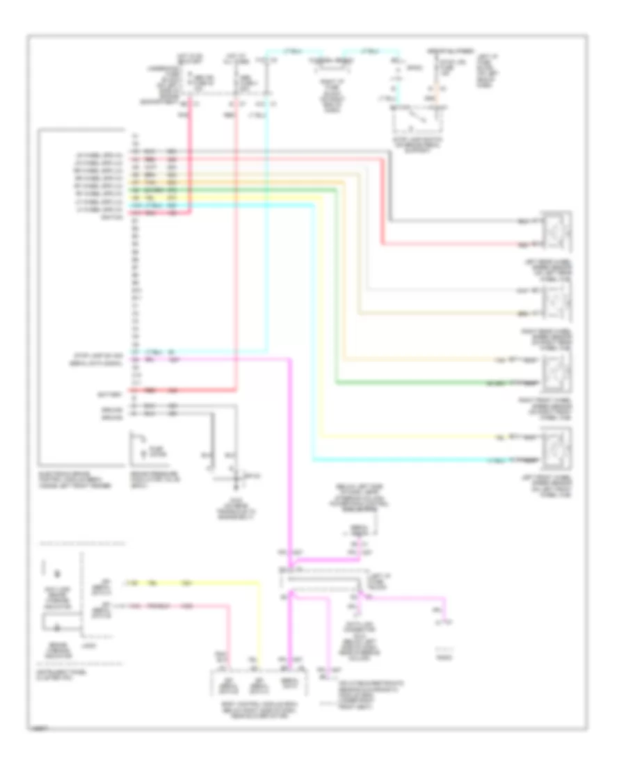
Anti-lock Brakes Wiring Diagram for Chevrolet Classic 2004
List of elements for Anti-lock Brakes Wiring Diagram for Chevrolet Classic 2004:
- (below left side of dash, near steering column) powertrain control module (pcm)
- A10
- A11
- A12
- Abs fuse 4 50a
- Abs ign fuse 40 10a
- Anti-lock brake warning indicator
- B10
- B11
- Battery
- Body control module (bcm) (below right side of dash, near blower motor)
- Brake pressure modulator valve (bpmv)
- Brake warning indicator
- C1 a1
- C10
- C11
- Data link connector (dlc) (below left side of dash, near steering column)
- Electronic brake control module (ebcm) (inside left front fender)
- F12
- G103 (on rear transaxle to engine bolt)
- Ground
- Hot at all times
- Hot in on or start
- Ignition
- Inflatable restraints sensing & diagnostic module (sdm) (under right front seat)
- Instrument panel cluster (ipc)
- Left front wheel speed sensor (on left front wheel hub)
- Left i/p fuse block
- Left i/p fuse block (on left end of dash)
- Left rear wheel speed sensor (on left rear wheel hub)
- Lf wheel spd (hi)
- Lf wheel spd (lo)
- Logic
- Lr wheel spd (hi)
- Lr wheel spd (lo)
- Nca
- Pnk
- Pump motor
- Radio
- Red
- Rf wheel spd (hi)
- Rf wheel spd (lo)
- Right front wheel speed sensor (on right front wheel hub)
- Right i/p fuse block (on right end of dash)
- Right rear wheel speed sensor (on right rear wheel hub)
- Rr wheel spd (hi)
- Rr wheel spd (lo)
- Serial data
- Serial data signal
- Sp103
- Sp303
- Spi serial data a
- Spi serial data b
- Stop lamp sw sig
- Stop lamp switch (on brake pedal support)
- Stop lps fuse 15a
- Tan
- Underhood fuse block (on left side of engine compartment)
 English