ANTI-LOCK BRAKES
Anti-lock Brake Wiring Diagrams for Chevrolet Corvette 1997
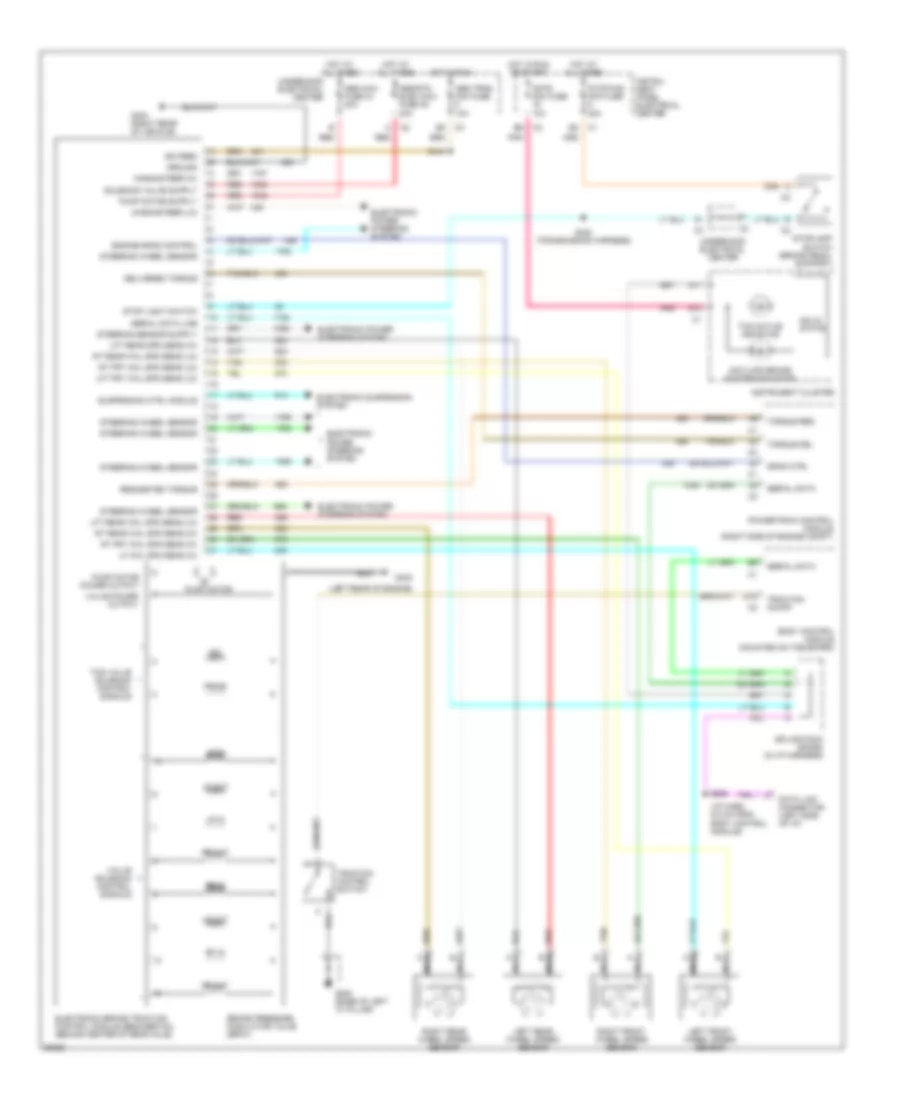
List of elements for Anti-lock Brake Wiring Diagrams for Chevrolet Corvette 1997:
- (i/p harn, 6.5 cm from body control module)
- (left rear of engine)
- A11
- A13
- Abs maxi fuse 44 40a
- Abs trns mini fuse 10a
- Abs/rtd elec maxi fuse 45 20a
- Antilock brake system indicator
- Body control module (mounted on toe board)
- Brake pressure modulator valve (bpmv)
- Cstr mini fuse 10a
- D15
- Data link connector (left side of i/p)
- Delivered torque
- Drag ctrl
- Electronic brake traction control module (ebcm/ebtcm) (behind center of rear axle)
- Electronic power steering system
- Electronic suspension system
- Engine drag control
- G200 (base of left "a" pillar)
- G402
- G403 (right rear of vehicle)
- Ground
- Hot at all times
- Hot in run
- Hot in run or start
- Ign feed
- Instru- ment panel electrical center
- Instrument cluster
- Iso
- Left front wheel speed sensor
- Left rear wheel speed sensor
- Lf in
- Lf out
- Lf whl spd sens (hi)
- Lft frt whl spd sens (lo)
- Lft rear spd sens (hi)
- Lft rear whl spd sens (lo)
- Lr in
- Lr out
- Magnasteer (hi)
- Magnasteer (lo)
- Nca
- Pnk
- Powertrain control module (right side of engine compt)
- Prime
- Pump motor
- Pump motor power output
- Red
- Requested torque
- Rf in
- Rf out
- Right front wheel speed sensor
- Right rear wheel speed sensor
- Rr in
- Rr out
- Rt frt whl spd sens (hi)
- Rt frt whl spd sens (lo)
- Rt rear whl spd sens (hi)
- Rt rear whl spd sens (lo)
- S208
- S418
- S420 (transmission harness)
- Serial data
- Serial data line
- Solid state
- Splice pack (sp206) (in i/p harness)
- Steering wheel sensor
- Stop light switch
- Stop/haz mini fuse 20a
- Stoplamp switch (brake pedal support)
- Suspension ctrl module
- Tan
- Tcs active indicator
- Tcs valve solenoid control signals
- Torque del
- Torque req
- Traction control switch
- Traction on/off
- Underhood electrical center
- Valve power output
- Valve solenoid control signals
 English