ANTI-LOCK BRAKES
Anti-lock Brakes Wiring Diagram for Chevrolet Venture LT 2004
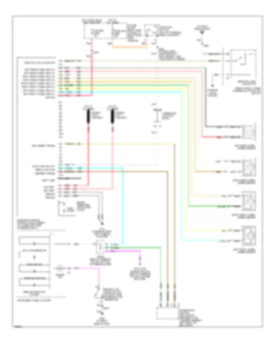
List of elements for Anti-lock Brakes Wiring Diagram for Chevrolet Venture LT 2004:
- (at right side of dash) g200
- A10
- A11
- Anti-lock brake ind
- B10
- B11
- Battery
- Brake fluid level switch (on right side of brake fluid reservoir)
- Brake ind
- Brake pressure modulator valve
- C10
- C11
- Data link connector (dlc) (below steering column, on knee bolster)
- Delivered torque
- Desired torque
- Electronic brake control module (ebcm) (at lower left side of engine compt)
- G114 (in engine compt, left & above starter)
- G200 (at right side of dash)
- Ground
- Hot at all times
- Hot in run, bulb test or start
- Ignition
- Instrument panel cluster
- Interior lights system
- Ip fuse block (right side of dash, in right front door opening)
- Left front wheel spd (hi)
- Left front wheel spd (lo)
- Left front wheel speed sensor
- Left rear wheel spd (hi)
- Left rear wheel spd (lo)
- Left rear wheel speed sensor
- Nca
- Pcm/abs fuse 10a
- Pnk
- Powertrain control module (pcm) (secured in air cleaner assembly, left front of eng compt)
- Pump motor
- Rear fog lamp/ tcs switch
- Rear window wiper/ washer multifunction switch
- Red
- Right front wheel spd (hi)
- Right front wheel spd (lo)
- Right front wheel speed sensor
- Right rear wheel spd (hi)
- Right rear wheel spd (lo)
- Right rear wheel speed sensor
- S108
- S205 (in dash harn, near breakout for harzard lamp/ turn signal flasher)
- S230
- S242
- Serial data sig
- Service traction system
- Sp205 (below steering column, bottom of knee bolster)
- Stop lamp sw out
- Stoplamp fuse 15a
- Stoplamp switch (on top of brake pedal support)
- Tan
- Trac off ind
- Traction active
- Traction ctrl on/off sig
- Underhood junction block
- Vent tube
 English