ANTI-LOCK BRAKES
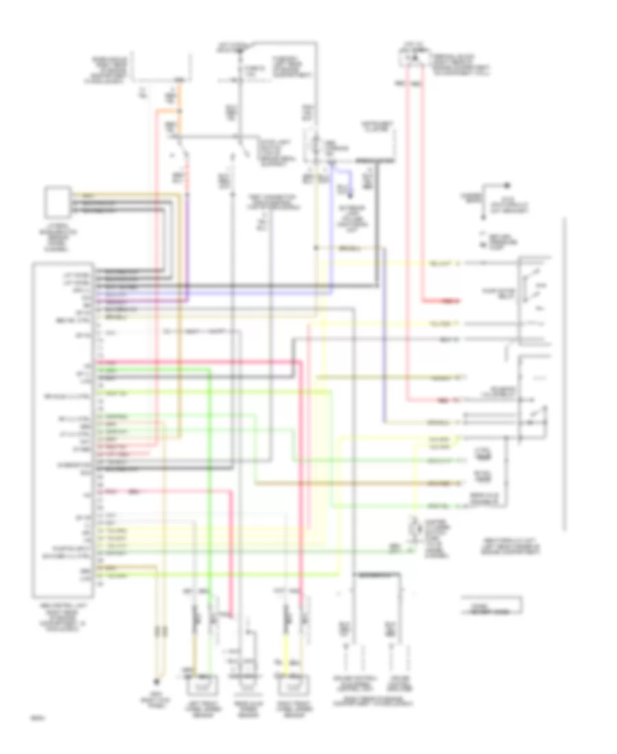
Anti-Lock Brakes Wiring Diagram for Mercedes-Benz 300SD 1993
List of elements for Anti-Lock Brakes Wiring Diagram for Mercedes-Benz 300SD 1993:
- & 500sel)
- (left rear corner of engine compartment)
- (on hydraulic unit bracket)
- (right kick
- (right rear
- (right rear of
- (right rear of engine compartment, in module box)
- ** pnk
- *300sd **except 300sd
- 61e
- 87-abs
- 87e
- Abs control unit
- Abs hydraulic unit
- Abs ind. ctrl
- Abs warning ind.
- Acceleration
- Base module
- Bls
- Braid
- Cluster
- Compartment,
- Control amplifier
- Control unit
- Copper
- Cruise
- Cruise control/
- Df ha
- Df vl
- Df vr
- Dfa vl
- Diagnostics
- Engine compartment, on component wall)
- Exterior lamp failure monitoring unit
- Fuse 23 7.5a
- Fuse box (left rear of engine compartment)
- G116
- G203
- Grd
- Hot at all times
- Hot in run
- Idle speed
- In module box)
- Instrument
- Lat accel
- Lateral
- Left front wheel speed sensor
- Lf sol valve
- Lf vlv ctrl
- Master cylinder switch- over valve (400sel & 500sel)
- May
- Mr-
- Nca
- Of engine
- Or start
- Panel)
- Pnk
- Pressure m
- Pump
- Pump motor relay
- Pump on input
- Rear axle sol valve
- Rear axle speed sensor
- Red
- Return/
- Rf sol valve
- Rf vlv ctrl
- Right front wheel speed sensor
- Rr axle vlv ctrl
- Sensor (400sel
- Solenoid valve relay
- Speedometer
- Stop light switch (top of brake pedal support)
- Sw-over vlv ctrl
- Terminal block
- Test connection for diagnosis (top of module box)
- Uvr
- Vvr
 English