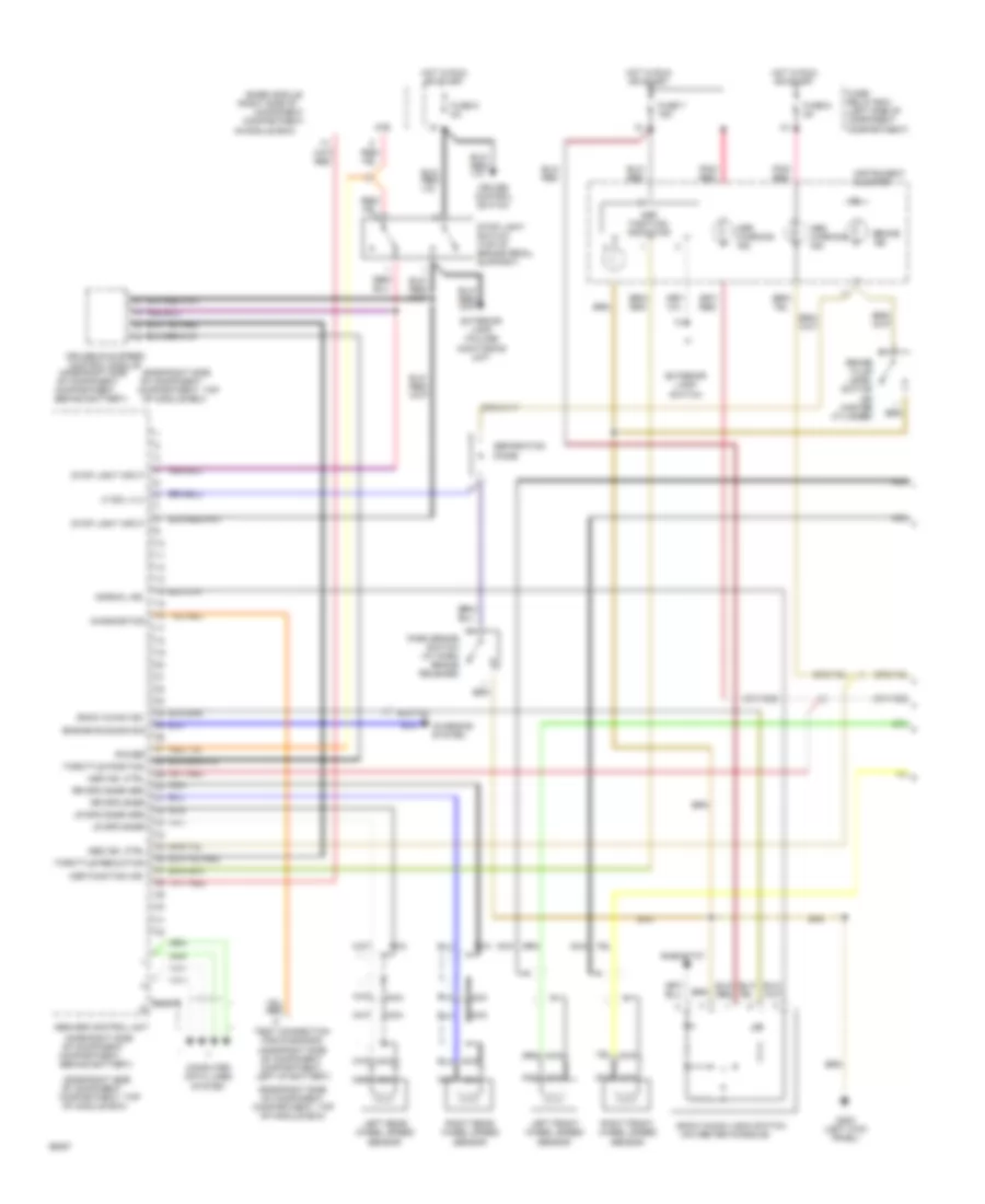
ANTI-LOCK BRAKES
Anti-Lock Brakes Wiring Diagram for Mercedes-Benz 500E 1993

List of elements for Anti-Lock Brakes Wiring Diagram for Mercedes-Benz 500E 1993:
- (400e-right side
- (500e-right side
- (left front corner of engine compartment)
- (on hydraulic unit bracket)
- (on intake manifold)
- (right side of
- 87e
- Abs control unit
- Abs hydraulic unit
- Abs ind. ctrl
- Abs warning ind.
- Base module
- Behind battery)
- Braid
- Brake light sw
- Charging system
- Compartment)
- Compartment,
- Compartment, top
- Component
- Computer data lines system
- Copper
- Cruise control switch
- Cruise/idle speed control module
- Diagnostics
- Differential rear speed sensor
- Engine running sig
- Exterior lamp failure monitoring unit
- Fuse 5 8a
- Fuse 6 8a
- Fuse/ relay box (left side of component compartment)
- G100
- G103
- G131
- Grd
- Ground
- Hot at all times
- Hot in run or start
- In module box)
- Instrument cluster
- Left front wheel speed sensor
- Left of battery)
- Lf sol valve
- Lf spd snsr
- Lf spd snsr grd
- Lf vlv ctrl
- Nca
- Of component
- Of component compartment,
- Of module box)
- Pnk
- Pnk/ red
- Power input
- Pump motor relay
- Pump on input
- Pump rly ctrl
- Rear axle sol valve
- Rear spd snsr
- Red
- Return pump
- Rf sol valve
- Rf spd snsr
- Rf spd snsr grd
- Rf vlv ctrl
- Right front wheel speed sensor
- Rly power
- Rr axle vlv ctrl
- Rr spd snsr grd
- Sol vlv rly ctrl
- Solenoid valve relay
- Stop light switch (top of brake pedal support)
- Terminal block (right side of component compartment)
- Test connection for diagnosis
- Throttle position
- Throttle reduction
- Twisted pair
- Twisted pairs
- Vlv relay status
Traction Control Wiring Diagram (1 of 2) for Mercedes-Benz 500E 1993
List of elements for Traction Control Wiring Diagram (1 of 2) for Mercedes-Benz 500E 1993:
- (400e-right side
- (400e-right side of component compartment, left of battery)
- (500e-right side
- (500e-right side of component compartment, top of module box)
- (on center console)
- (right side of
- 87e
- Abs ind. ctrl
- Abs warning ind.
- Abs/asr control unit
- Asr function ind.
- Asr function indicator
- Asr ind. ctrl
- Asr warning ind.
- Base module
- Behind battery)
- Brake fluid level switch (on master cylinder)
- Brake ind.
- Charging system
- Compartment,
- Compartment, top
- Component
- Computer data lines system
- Cruise control switch
- Cruise/idle speed control module
- Diagnostics
- Engine running sig
- Exterior lamp failure monitoring unit
- Exterior lamp switch
- Fuse 5 8a
- Fuse 6 8a
- Fuse 7 16a
- Fuse/ relay box (left side of component compartment)
- G200 (left kick panel)
- Hot in run or start
- In module box)
- Instrument cluster
- Left front wheel speed sensor
- Left rear wheel speed sensor
- Lf sol vlv
- Lr spd snsr
- Lr spd snsr grd
- Nca
- Normal ind.
- Of component
- Of component compartment,
- Of module box)
- Park brake switch (at park brake release)
- Pnk/ red
- Power
- Rheostat
- Right front wheel speed sensor
- Right rear wheel speed sensor
- Rr spd snsr
- Rr spd snsr grd
- Separation diode
- Snow chain ind.
- Snow chain logic switch
- Stop light input
- Stop light switch (top of brake pedal support)
- Test connection for diagnosis
- Throttle position
- Throttle reduction
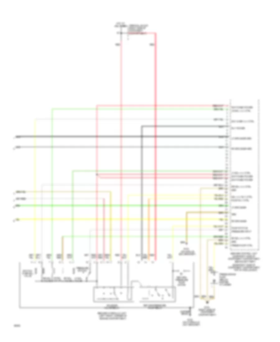
Traction Control Wiring Diagram (2 of 2) for Mercedes-Benz 500E 1993
List of elements for Traction Control Wiring Diagram (2 of 2) for Mercedes-Benz 500E 1993:
- (500e-right side of component compartment,
- (left front corner of engine compartment)
- (on hydraulic unit bracket)
- (on module
- (right side of
- Abs/asr control unit (400e-right side of component compartment,
- Abs/asr hydraulic unit
- Behind battery)
- Box bracket)
- Compartment)
- Component
- Copper braid
- Cylinder)
- G100
- G103
- Grd
- Hot at all times
- Lf sol valve
- Lf sol vlv ctrl
- Lf spd snsr
- Lf spd snsr grd
- Lr sol valve
- Lr sol vlv ctrl
- Nca
- Press pump ctrl
- Pressure input
- Pressure switch
- Pressurizing
- Pump (below master
- Pump relay
- Pump rly ctrl
- Pump status
- Red
- Return/ pressure pump motor
- Return/pressure
- Rf sol valve
- Rf sol vlv ctrl
- Rf spd snsr
- Rf spd snsr grd
- Rly power
- Rr sol valve
- Rr sol vlv ctrl
- Sol vlv rly ctrl
- Solenoid
- Sw/ over vlv ctrl
- Switch- over sol valve
- Switched power
- Terminal block (right side of component compartment)
- Top of module box)
- Valve relay