ANTI-LOCK BRAKES
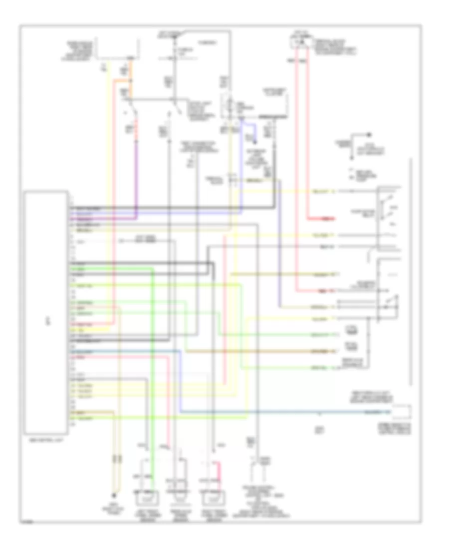
Anti-lock Brake Wiring Diagrams, without Acceleration Slip Regulation or Traction Control for Mercedes-Benz S350 1994
List of elements for Anti-lock Brake Wiring Diagrams, without Acceleration Slip Regulation or Traction Control for Mercedes-Benz S350 1994:
- (left rear corner of engine compartment)
- (on hydraulic unit bracket)
- (right kick
- (right rear
- (right rear of
- (right rear of engine compartment, in module box)
- (s320)
- (s350)
- (s350) (s320)
- 61e
- 87e
- Abs control unit
- Abs hydraulic unit
- Abs warning ind.
- Base module
- Braid
- Cc control
- Cluster
- Compartment,
- Control unit
- Copper
- Cruise control/
- Engine compartment, on component wall)
- Exterior lamp failure monitoring unit
- Fuse 23 10a
- Fuse box
- G116
- G203
- Hot at all times
- Hot in run
- Idle speed
- In module box)
- Instrument
- Left front wheel speed sensor
- Lf sol valve
- Module
- Nca
- Of engine
- Or start
- Panel)
- Pnk
- Pressure m
- Pump
- Pump motor relay
- Rear axle sol valve
- Rear axle speed sensor
- Red
- Return/
- Rf sol valve
- Right front wheel speed sensor
- S320 only
- Solenoid valve relay
- Speed sensitive power steering control module
- Speedometer
- Stop light switch (top of brake pedal support)
- Terminal block
- Test connection for diagnosis (top of module box)