ANTI-LOCK BRAKES
Anti-lock Brakes Wiring Diagram (1 of 2) for Mercedes-Benz SLK230 2003

List of elements for Anti-lock Brakes Wiring Diagram (1 of 2) for Mercedes-Benz SLK230 2003:
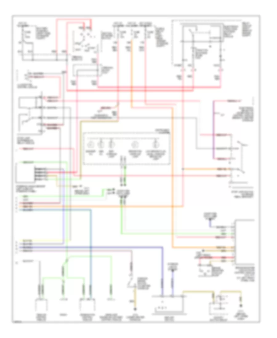
Anti-lock Brakes Wiring Diagram (2 of 2) for Mercedes-Benz SLK230 2003
List of elements for Anti-lock Brakes Wiring Diagram (2 of 2) for Mercedes-Benz SLK230 2003: