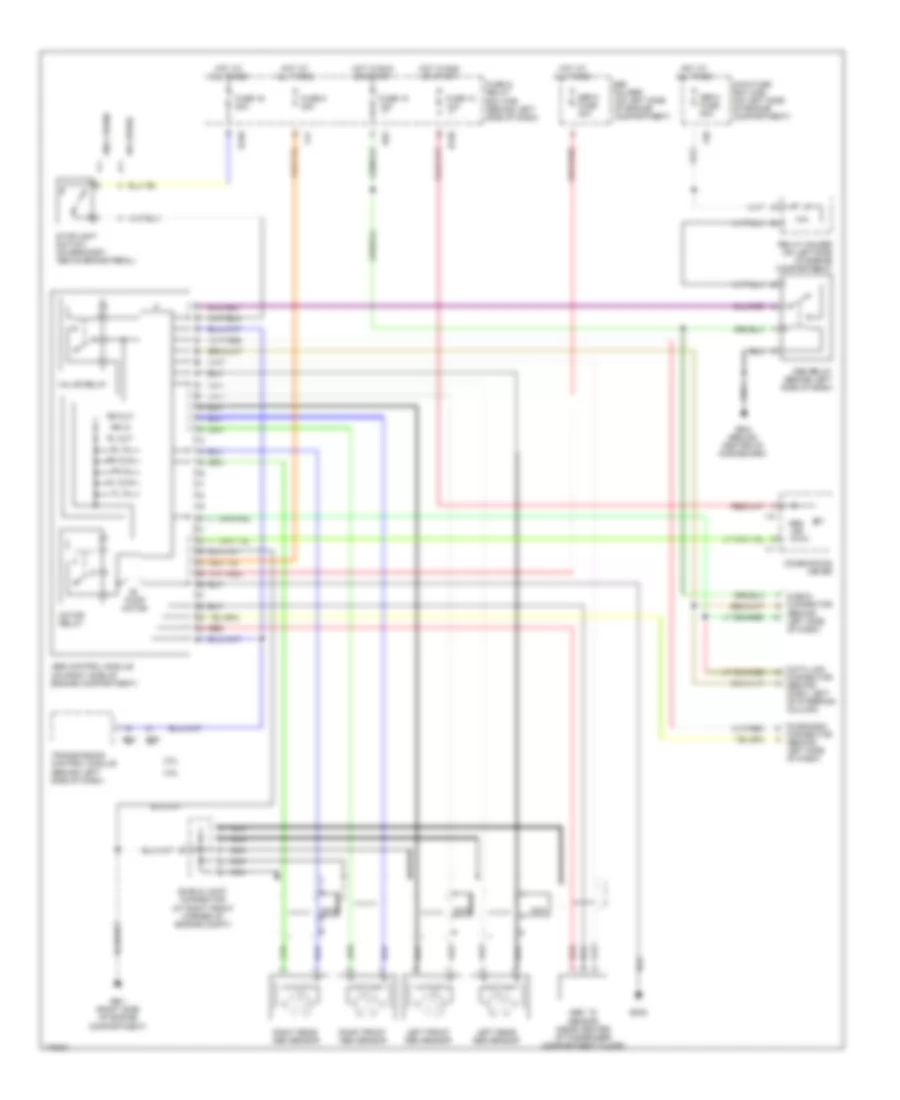
ANTI-LOCK BRAKES
Anti-lock Brakes Wiring Diagram for Subaru Impreza WRX 2003
List of elements for Anti-lock Brakes Wiring Diagram for Subaru Impreza WRX 2003:
- (behind left side of dash)
- 10a
- 2.0l
- 2.5l
- Abs control module (on right side of engine compartment)
- Abs ind
- Abs relay (behind left side of dash)
- Abs ``g" sensor (near center of passenger compartment floor)
- B158
- B302
- B52
- B54
- B55
- Check connector
- Combination meter
- Connector (behind left side of dash)
- Data link connector (behind dash, left of steering column)
- Diagnosis
- F38
- F41
- Fl in
- Fl out
- Fr in
- Fr out
- Fuse & relay box (f/b) (behind left side of dash)
- Fuse 13 10a
- Fuse 16 20a
- Fuse 18 15a
- Fuse 8 20a
- Gb-1 (right side of engine compartment)
- Gb-5 (behind center of dashboard)
- Hot at all times
- Hot in run or start
- I10
- I11
- Left front abs sensor
- Left rear abs sensor
- Main fuse box (m/b) (on left side of engine compartment)
- Motor relay
- Nca
- Pump motor
- Red
- Relay holder (on left side of engine compartment)
- Right front abs sensor
- Right rear abs sensor
- Rl in
- Rl out
- Rr in
- Rr out
- Sbf holder (on left side of engine compartment)
- Sbf-4 fuse 50a
- Sbf-8 fuse 30a
- Shield joint connector (at right front corner of engine compt)
- Stoplight switch (on bracket, above brake pedal)
- Transmission control module (behind left side of dash)
- Valve relay
- W/ cruise
- W/o cruise
 English