ANTI-LOCK BRAKES
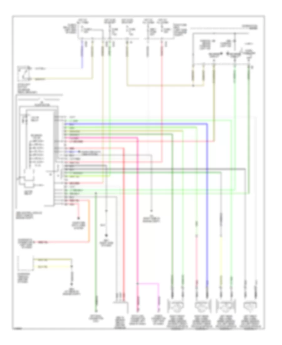
Anti-lock Brakes Wiring Diagram, without VDC for Subaru Legacy i 2005
List of elements for Anti-lock Brakes Wiring Diagram, without VDC for Subaru Legacy i 2005:
- (left side of dash)
- Abs "g" sensor (below center console)
- Abs control module (right side of engine compt)
- Abs warning light ind
- B144
- B152
- B158
- B159
- Check connector (left end of dash)
- Combination meter
- Computer data lines system
- Data link connector (under left side of dash)
- Diagnosis terminal (center of dash)
- Diagnostic connector
- Fl in
- Fl out
- Fr in
- Fr out
- Fuse & relay box (left end of dash)
- Fuse 1 30a
- Fuse 15a
- Fuse 7.5a
- Fuse 8 20a
- Ga (right side of engine compt)
- Gb-4 (at rear of engine compt)
- Gb-7 (right side of dash)
- Hot at all times
- Hot in on or start
- I/f
- I10
- Left front abs wheel speed sensor (on left front knuckle spindle assembly)
- Left rear abs wheel speed sensor (on left rear knuckle spindle assembly)
- Main fuse box (left side of engine compt)
- Micro computer
- Motor relay
- Nca
- Optional connector (2.5l)
- Parking brake warning light ind
- Pnk
- Pump motor
- Red
- Reverse circuit
- Right front abs wheel speed sensor (on right front knuckle spindle assembly)
- Right rear abs wheel speed sensor (on right rear knuckle spindle assembly)
- Rl in
- Rl out
- Rr in
- Rr out
- Sbf-1 fuse 50a
- Solenoid valve
- Stoplight switch (on brake pedal bracket)
- Valve relay
 English