ANTI-LOCK BRAKES
Anti-lock Brake Wiring Diagrams, with Traction Control for Volvo 850 Turbo 1994
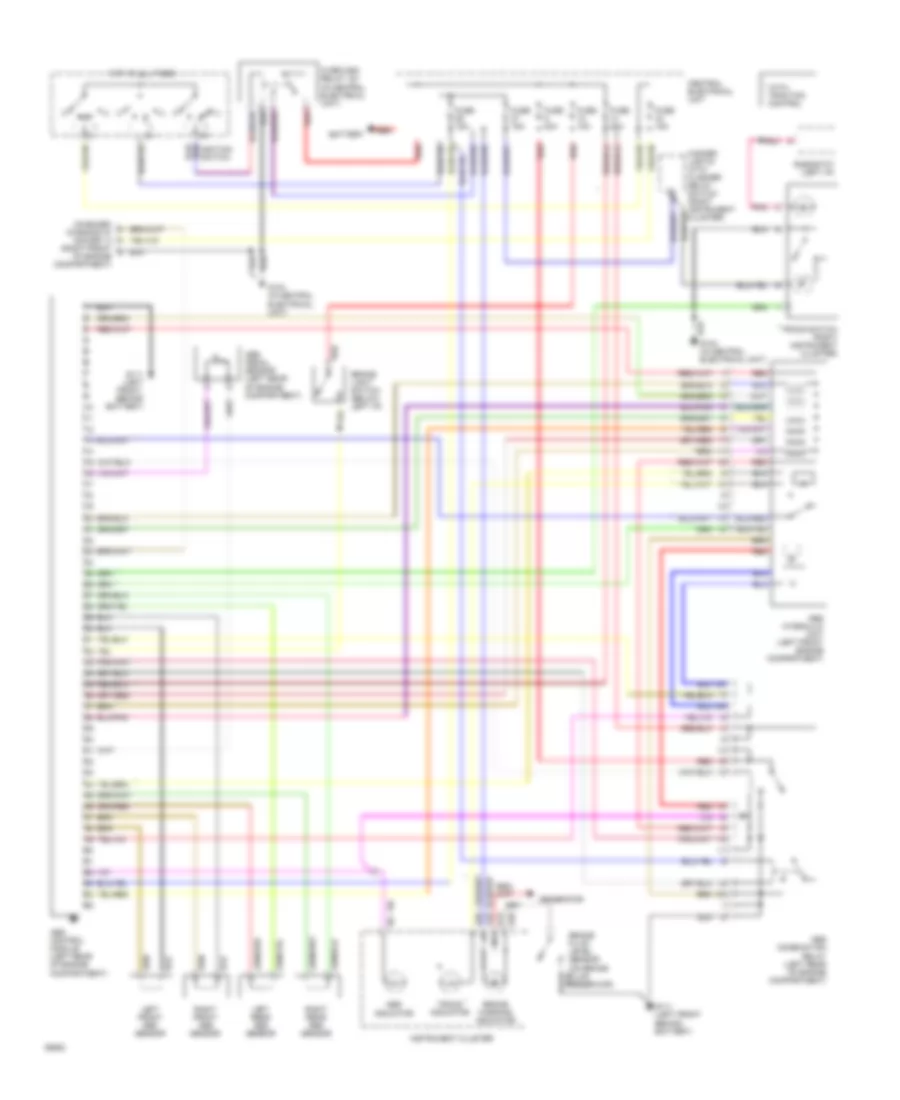
List of elements for Anti-lock Brake Wiring Diagrams, with Traction Control for Volvo 850 Turbo 1994:
- (in central electrical unit)
- (on brake fluid reservoir)
- (right front
- * with traction control
- 15i
- A13
- A18
- A28
- A29
- Abs combination relay (left rear of engine compartment)
- Abs control module (left rear of engine compartment)
- Abs hydraulic unit (left front engine compartment)
- Abs indicator
- Abs pedal sensor (left rear of engine compartment)
- Battery
- Brake fluid level sensor
- Brake light switch (below left i/p)
- Brake warning indicator
- Central electrical unit
- Fuse 10a
- Fuse 15a
- Fuse 30a
- G104 (in central electrical unit)
- G111 (left front behind battery)
- G111 (left front, behind battery)
- Generator
- Hazard lights with flasher relay switch (right instrument cluster)
- Hot at all times
- Ignition switch
- Iii
- Instrument cluster
- Left front abs sensor
- Left rear abs sensor
- Of engine compartment)
- On-board diagnostic socket a
- Overload relay 15+ (in central electrical unit)
- Pnk
- Red
- Rheostat (left i/p)
- Right front abs sensor
- Right rear abs sensor
- Tracs indicator
- Tracs switch (right instrument cluster)
 English