ANTI-LOCK BRAKES
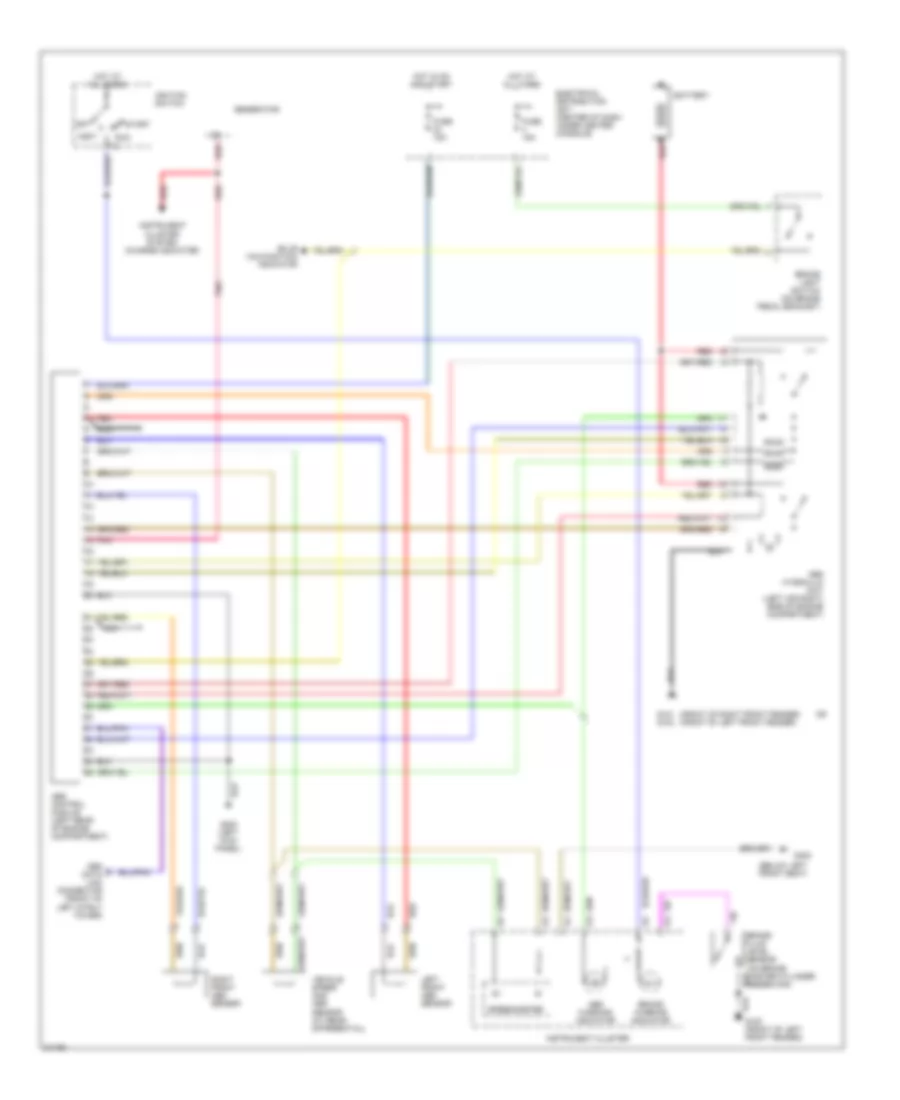
Anti-lock Brake Wiring Diagrams for Volvo 940 1995
List of elements for Anti-lock Brake Wiring Diagrams for Volvo 940 1995:
- (below left front seat)
- (front of right front fender) (front of left front fender)
- Abs control module (left rear of engine compartment)
- Abs hydraulic unit (left (or right) side of engine compartment)
- Abs warning indicator
- Accy
- Battery
- Brake fluid level sensor (on brake master cylinder reservoir)
- Brake light switch (on brake pedal bracket)
- Brake warning indicator
- Bulb malfunction indicator
- Electrical distribution unit (center of dash under center console)
- Fuse 15a
- G101 g100
- G200 (left kick panel)
- G300
- Generator
- Hot at all times
- Hot in on and start
- Ignition switch
- Instrument cluster
- Instrument cluster system (charge indicator)
- Left front abs sensor
- Nca
- Obd data link connector (front of left strut tower)
- Off
- Pnk
- Red
- Right front abs sensor
- Run
- Speedometer
- Start
- Vehicle speed and abs sensor (at rear differential)
 English