ANTI-LOCK BRAKES
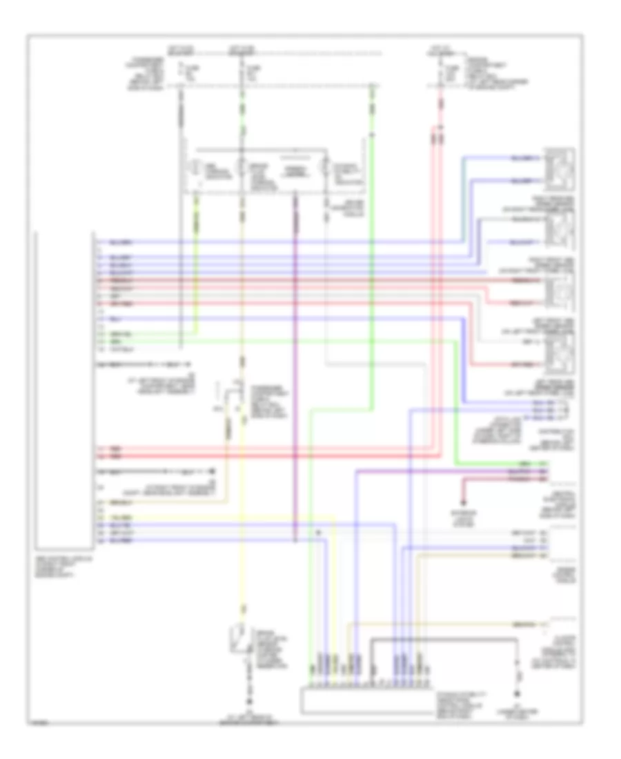
Anti-lock Brakes Wiring Diagram for Volvo S40 LSE 2004
List of elements for Anti-lock Brakes Wiring Diagram for Volvo S40 LSE 2004:
- A17
- Abs control module (in right front corner of engine compt)
- Abs warning indicator
- B14
- B16
- B22
- Brake fluid level sensor (in brake master cylinder reservoir)
- Brake fluid level warning indicator
- Central electronic module (behind left side of dash)
- Climate control module (ccm) (integral to a/c controls, in center of dash)
- Data link connector (under left side of dash, right of steering column)
- Distribution rail (behind left center of dash)
- Driver information module
- Dynamic stability assistance control module (behind right end of dash)
- Dynamic stability on indicator
- E11
- E12
- Engine compartment fuse & relay box (at left rear corner of engine compt)
- Engine control module
- Exterior lights system
- Fuse a15 50a
- Fuse b11 10a
- Fuse b4 10a
- G4 (at left rear of engine compartment)
- G7 (under center of dash)
- G8 (at left front of engine compartment, near headlight assembly)
- G9 (at right front of engine compt, near headlight assembly)
- Hot at all times
- Hot in on or start
- I10
- I14
- Left front abs speed sensor (on left front wheel hub)
- Left rear abs speed sensor speed sensor (on left rear wheel hub)
- Passenger compartment fuse & relay box (behind left side of dash)
- Red
- Right front abs speed sensor (on right front wheel hub)
- Right rear abs speed sensor (on right rear wheel hub)
- Speedo- meter
 English