ANTI-THEFT
Anti-theft Alarm Wiring Diagram for Volvo V40 2002

List of elements for Anti-theft Alarm Wiring Diagram for Volvo V40 2002:
- (behind left headlamp) g8
- (left rear side of cargo compt) g10 g12
- (left side of dash) g1
- (right rear side of cargo compt) g11 g12
- (s40) (v40)
- A10
- A12
- A13
- A16
- A18
- A19
- A20
- A22
- A23
- A24
- A26
- Alarm siren (left front of engine compt)
- B10
- B11
- B14
- B15
- B16
- B19
- C10
- Cargo compartment area, lighting/ alarm contact
- Computer data lines system
- Distribution rail (left side of dash)
- Driver door contact
- Driver's door central locking switch
- Driver's door lock switch
- Driver's door power windows/ mirrors switch unit
- E10
- Engine compartment fuse & relay box (in left rear corner of engine compt)
- Exterior lights system
- F10
- Fuse 10a
- Fuse 15a
- Fuse 20a
- G1 (left side of dash)
- G15
- G9 (behind right headlamp)
- Glass breakage sensor (on roof, at center of windshield)
- Hood alarm contact
- Hot at all times
- Hot in on
- Hot in on or start
- Interior lights system
- Key- inserted warning contact
- Left rear door contact
- Passenger compartment fuse & relay box (behind left end of dash)
- Passenger door central locking switch
- Passenger door contact
- Pnk
- Red
- Right rear door contact
- Ultrasonic glass breakage sensor (below right side of dash)
- Vgla control module (behind lower center of dash)
- Vgla receiver (in rear of engine compt)
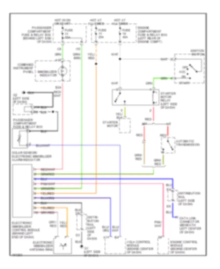
Immobilizer Wiring Diagram for Volvo V40 2002
List of elements for Immobilizer Wiring Diagram for Volvo V40 2002:
- (left side of dash)
- A/t
- A11
- A17
- Acc
- Automatic transmission
- B24
- Combined instrument panel
- Data link connector (beneath left center of dash)
- Distri- bution rail (left side of dash)
- Distribution rail (left side of dash)
- Electronic immobilizer antenna ring
- Electronic immobilizer control module (behind left end of dash)
- Engine compartment fuse & relay box (left rear of engine compt)
- Engine control module (behind center of dash)
- Fuse 10a
- Fuse 20a
- Fuse 40a
- Hot at all times
- Hot in on or start
- I15
- Ignition switch
- Immobilizer indicator
- M/t
- Off
- Passenger compartment fuse & relay box
- Passenger compartment fuse & relay box (behind left end of dash)
- Red
- Solar sensor/ electronic immobilizer alarm indicator
- Start
- Starter motor
- Starter motor relay (left side of dash)
- Vgla control module (behind center of dash)