COMPUTER DATA LINES
Computer Data Lines Wiring Diagram for Acura 2.5TL 1998
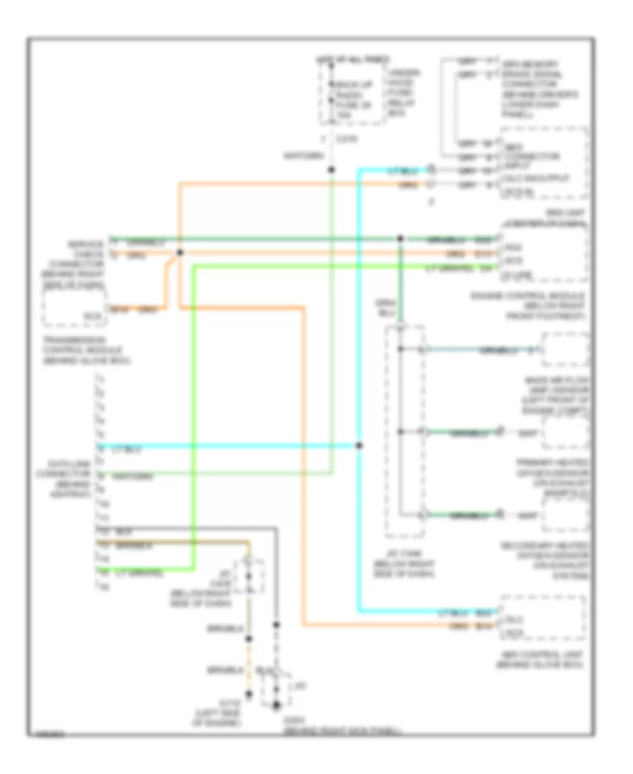
List of elements for Computer Data Lines Wiring Diagram for Acura 2.5TL 1998:
- (behind ashtray)
- Abs control unit (behind glove box)
- B14
- B22
- Back up radio fuse 39 10a
- C216
- Connector (behind driver's lower dash panel)
- Connector (behind right side of dash)
- D13
- D22
- Data link connector
- Dlc
- Dlc in/output
- Engine control module (below right front footrest)
- G112 (left side of engine)
- G203 (behind right kick panel)
- Hot at all times
- J/c
- J/c c436 (below right side of dash)
- J/c c444 (below right side of dash)
- K-line
- Mass air flow (maf) sensor (left front of engine compt)
- Mes connector input
- Primary heated oxygen sensor (on exhaust manifold)
- Scs
- Scs in
- Secondary heated oxygen sensor (on exhaust system)
- Service check
- Sg2
- Srs memory erase signal
- Srs unit (center of dash)
- Transmission control module (behind glove box)
- Under- hood fuse/ relay box
 English