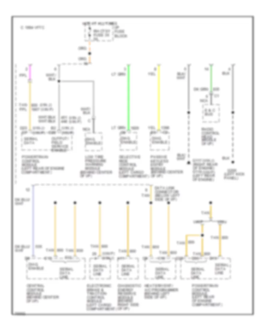
COMPUTER DATA LINES
Data Link Connector Wiring Diagram for Chevrolet Corvette ZR-1 1995
List of elements for Data Link Connector Wiring Diagram for Chevrolet Corvette ZR-1 1995:
- (behind center of i/p)
- (left kick panel)
- (vin j)
- (vin j) (vin p)
- (vin p)
- (vin p) (vin j)
- 1994 vftc c
- A11
- B2 d20
- C10
- Central control module (behind center of i/p)
- D15
- D20 d7
- D29
- D30
- Data link connector (below left side of i/p)
- Diag. enable
- Diagnostic energy reserve module (behind right side of i/p)
- E & c bus
- E13
- Electronic brake & traction control module (left cargo compartment)
- F12
- G117 (right rear of engine) g114 (left rear of engine)
- G200
- Heater/vent/ a/c programmer (behind left side of i/p)
- Hot at all times
- I/p fuse block
- Low tire pressure warning module
- Nca
- Output/ field service enable
- Passive keyless entry module (behind center of i/p)
- Powertrain control module (left rear of engine compartment)
- Radio control head (middle of i/p)
- Rh ctsy fuse 36 5a
- Selective ride control module (left cargo compartment)
- Serial data
- Serial data line
- Tan
- Vin j
- Vin p
 English