COMPUTER DATA LINES
Diagnostic Socket Wiring Diagram for Mercedes-Benz S500 1994

List of elements for Diagnostic Socket Wiring Diagram for Mercedes-Benz S500 1994:
- (left
- (right
- Acc
- Bank)
- Center (tdc) sensor
- Coil 1
- Coil wire
- Cylinder
- Diagnostic socket (left side of engine compt)
- Distributor
- Fuse 17 20a
- Fuse box
- G102 (left front shock tower)
- Hot at all times
- Ignition
- Ignition coil 2
- Ignition control module
- Ignition/ starter switch
- Left high voltage
- Lh control unit
- Lock
- Nca
- Right high voltage
- Run
- Start
- Top dead
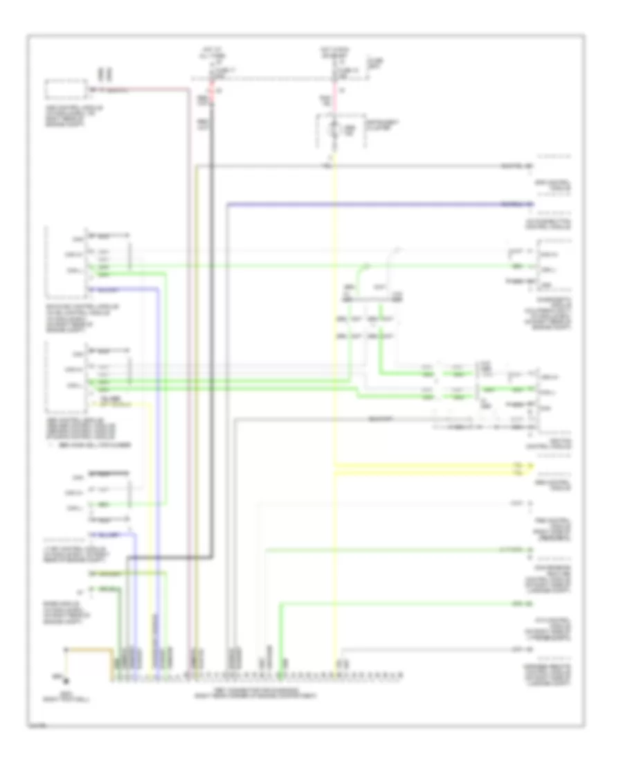
Test Connector Wiring Diagram for Mercedes-Benz S500 1994
List of elements for Test Connector Wiring Diagram for Mercedes-Benz S500 1994:
- (1994)
- (1995)
- (in module box, on right rear of engine compt)
- A/c pushbutton control module
- Abs control module/ abs/asr control module/ asr/sps control module/ ets/sps control module
- Ads control module (in module box, on right rear of engine compt)
- Ata control module (on right side of luggage compt)
- Base module
- Can
- Can h+
- Can l-
- Cc/isc control module
- Convenience feature control module (on right side of luggage compt)
- Diagnogstic module (california only) (in module box, on right rear of engine compt)
- Ea/cc/isc control module/
- Fuse 15 15a
- Fuse 17 20a
- Fuse box
- G203 (right footwell)
- Hot at all times
- Hot in run or start
- Ignition control module
- Infrared remote control module (on right side of luggage compt)
- Instrument cluster
- Lt-sfi control module (in module box, on right rear of engine compt)
- Nca
- Pse control module (right side of rear seat)
- See home cell for number
- Sps control module
- Srs control module
- Srs ind
- Test connector for diagnosis (right rear corner of engine compartment)
- W/ asr
- W/o asr