COMPUTER DATA LINES
Data Link Connector Wiring Diagram for Mercedes-Benz S500 4Matic 2006

List of elements for Data Link Connector Wiring Diagram for Mercedes-Benz S500 4Matic 2006:
- 81a
- 84a
- Abc control module
- Airmatic w/ ads control module
- Can-b h
- Can-b l
- Can-c h
- Can-c l
- Can-d h
- Can-d l
- Central gateway control module
- Cockpit fuse box
- Comand operating, display & control module
- Connectors 1-6 not used
- Data link connector (at upper left footwell)
- Di control module
- Diag
- Dtr control module
- Electronic control unit (vgs)
- Electronic selector lever control module (under center console, at base of selector lever assembly)
- Emergency call system control unit
- Engine control module (me-sfi) (right rear of engine compt)
- Esp/sps/bas control module
- Etc control module (right rear of engine compt)
- Fuse 10a
- Fuse 5a
- Headlamp range adjustment control module
- High/low bus circuit
- Hot at all times
- Hot in run or start
- Instrument cluster
- Left front headlamp unit
- Left front reversible emergency tensioning retractor
- Nca
- Right front headlamp unit
- Right front reversible emergency tensioning retractor
- Shield
- Steering column module (at top of steering column)
- Tele aid control module
- W/ 7-speed automatic transmission
- W/ abc
- W/ airmatic
- W/ electronic transmission control
- W36/2 (at right front footwell)
- Xenon headlamp control module
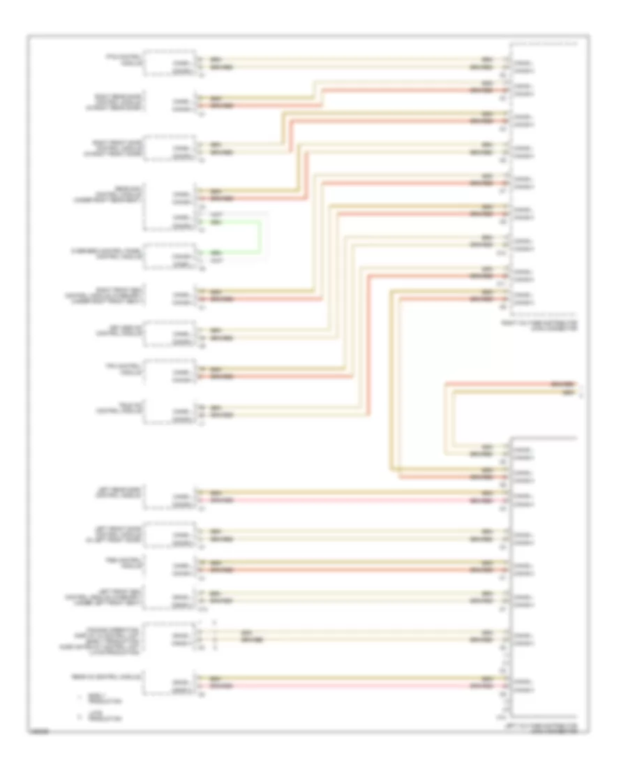
High/Low Bus Wiring Diagram (1 of 2) for Mercedes-Benz S500 4Matic 2006
List of elements for High/Low Bus Wiring Diagram (1 of 2) for Mercedes-Benz S500 4Matic 2006:
- C10
- C11
- C13
- Can-b h
- Can-b l
- Comand operating, display & control unit (early production) audio gateway control unit (late production)
- Early production
- Keyless go control module
- Late production
- Left front door control module (in left front door)
- Left front esa control module (w/memory) (under left front seat)
- Left rear door control module
- Left voltage distributor (can) connector
- Overhead control panel control module
- Pse control module
- Pts control module
- Rear ac control module
- Rear sam control module (under right rear seat)
- Right front door control module (in right front door)
- Right front esa control module (w/memory) (under right front seat)
- Right rear door control module (in right rear door)
- Right voltage distributor (can) connector
- Tele aid control module
- Tpm control module
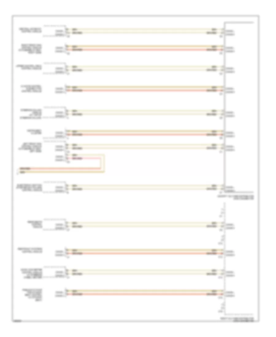
High/Low Bus Wiring Diagram (2 of 2) for Mercedes-Benz S500 4Matic 2006
List of elements for High/Low Bus Wiring Diagram (2 of 2) for Mercedes-Benz S500 4Matic 2006:
- C12
- C13
- C14
- C15
- C16
- Can-b h
- Can-b l
- Central gateway control module
- Climate control pushbutton control module
- Cockpit voltage distributor (can) connector
- Dc/dc converter control module (w/ steering wheel heater)
- Electronic ignition- starter switch (eis) control module
- Instrument cluster
- Left front sam control module (in fuse/relay box, left side)
- Pneumatic pump for dynamic seat control (w/ dynamic seat)
- Rear seats control module
- Restraint systems control module
- Right front sam control module (in fuse/relay box, right side)
- Right voltage distributor (can) connector
- Steering column module (at top of steering column)
- Upper control field control module