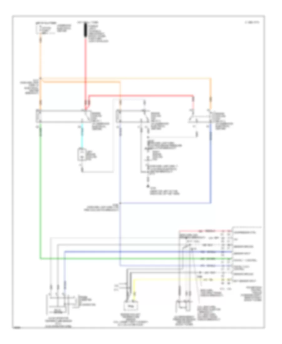
COOLING FAN
Cooling Fan Wiring Diagram for Chevrolet Camaro RS 1997
List of elements for Cooling Fan Wiring Diagram for Chevrolet Camaro RS 1997:
- (3.8l)
- (3.8l: eng harn, 6cm from injector 1 breakout) (5.7l: eng harn, 4cm from trans- mission breakout)
- (5.7l on water pump)
- (eng harn, 14cm from trans- mission breakout)
- (eng harn, 8cm from pcm breakout)
- (in evaporator core)
- (in underhood electrical center)
- (near top left of the
- +5v
- 3.8l
- 5.7l
- A/c evaporator temperature sensor (5.7l)
- A/c refrigerant pressure sensor (above right shock tower)
- A/p fan fuse 7 25a
- C 1995 vftc
- Compressor ctrl
- Ect sensor input
- Engine coolant temperature sensor (3.8l: under throttle body)
- Engine cooling fan relay 1
- Engine cooling fan relay 2 (in underhood electrical center)
- Engine cooling fan relay 3 (in underhood electrical center)
- Fan rly 1 control
- Fan rly 2 & 3 control
- G108
- Hot at all times
- Left engine cooling fan
- Powertrain control module (in engine compt, rear of right shock tower)
- Probe (inserted in evaporator)
- Radiator, on the t-bar)
- Red
- Right engine cooling fan
- S117
- S119
- S122
- S166 (forward lamp harn, 4 cm from cooling fan breakout)
- S177 (forward lamp harn, in electrical center breakout)
- Sensor ground
- Sensor input
- Solid state
- Underhood electrical center
 English