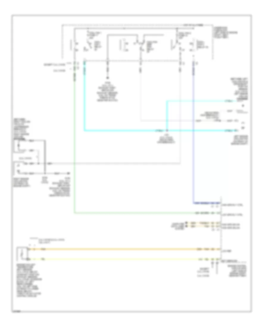
COOLING FAN
Cooling Fan Wiring Diagram, with Hybrid for Chevrolet Malibu LT 2008

List of elements for Cooling Fan Wiring Diagram, with Hybrid for Chevrolet Malibu LT 2008:
- (behind rear seat) generator battery vent fan
- (middle rear of engine) heater coolant pump
- (near windshield wiper fluid reservoir) g101
- (next to a/c compressor) starter generator control module (sgcm) coolant pump
- (right front of transmission, below sgcm) transmission pump
- (under right rear seat back) g301
- A trans pump driver error
- A12
- B pump control
- B10
- Bare
- Bas ign fuse 3 10a
- Bas pmps fuse 5 20a
- Battery positive vol
- C pump motor vol
- C12
- Computer data lines system
- Driver error
- Emission 2 fuse 5 10a
- Eng/tran cooling
- F trans pump low ref
- Fan control
- Fan tach feedback
- G trans pump high ref
- G107 (near sgcm cooling pump)
- Gen batt temp sens 1a control
- Gen batt temp sens 1b control
- Gen batt temp sens 2a control
- Gen batt temp sens 2b control
- Gen batt temp sens 3a control
- Gen batt temp sens 3b control
- Generator battery 1
- Generator battery 2
- Generator battery 3
- Generator battery assembly (behind rear seat, above spare tire)
- Generator battery disconnect control module
- Generator battery temperature sensor 1a
- Generator battery temperature sensor 1b
- Generator battery temperature sensor 2a
- Generator battery temperature sensor 2b
- Generator battery temperature sensor 3a
- Generator battery temperature sensor 3b
- Gnd
- Ground
- H trans pump sw control
- High speed gmlan serial data +
- High speed gmlan serial data -
- High vol
- Hot at all times
- Hot in run or start
- Ignition 1 vol
- Interlock loop sig
- Low ref
- Motor vol
- Nca
- Pnk
- Power
- Power distribution system
- Pump
- Pump control
- Pump driver (left front of engine, behind sgcm)
- Rear fuse block (in left side of luggage compt, behind left rear wheel well)
- Red
- Starter generator control module (sgcm) (in left front engine compt, behind headlamp assembly)
- Tan
- Trans pmp mtr relay
- Trans pump
- Trans pump mtr fuse 52 20a
- Trans pump rly coil control
- Underhood fuse block (on left side of engine compt)
- X2 interlock loop sig
Cooling Fan Wiring Diagram, without Hybrid for Chevrolet Malibu LT 2008
List of elements for Cooling Fan Wiring Diagram, without Hybrid for Chevrolet Malibu LT 2008:
- (2.4l (vin 5))
- (355 mm from main breakout) (2.4l (vin 5)) j153
- (between left cooling fan & crankshaft position sensor) (2.4l (vin 5)) left engine cooling fan diode
- (between right cooling fan & a/c compressor breakout) (2.4l (vin 5)) right engine cooling fan diode
- 2.4l (vin b)
- 2.4l (vin b) & 2.4l (vin 5) 3.6l (vin 7)
- 87a
- A11
- B10
- Computer data lines system
- Cool fan 1 fuse 17 30a
- Cool fan 2 fuse 18 30a
- Cool/ fan 1 relay
- Cool/ fan 2 relay 30
- Cool/fan ser/ par relay
- Ect sens sig
- Engine control module (ecm) (left side of engine compt, near battery)
- Engine coolant temperature (ect) sensor (2.4l (vin 5): below camshaft position exhaust sensor) (2.4l (vin b): on engine block, at left rear corner) (3.6l: on left side of front cylinder head, below throttle actuator control module)
- Except 2.4l (vin b)
- G106 (2.4l: at 4 exhaust port, above cmp exhaust sensor) (3.6l: on trans- mission stud, near pnp switch)
- High spd gmlan
- High spd rly ctrl
- Hot at all times
- J151 (2.4l (vin 5)) (305 mm from main breakout)
- Left engine cooling fan (on front of engine compt)
- Low ref
- Low spd rly ctrl
- Right engine cooling fan (on front of engine compt)
- S152 (2.4l (vin 5))
- Tan
- Underhood fuse block (left side of engine compt, next to battery)