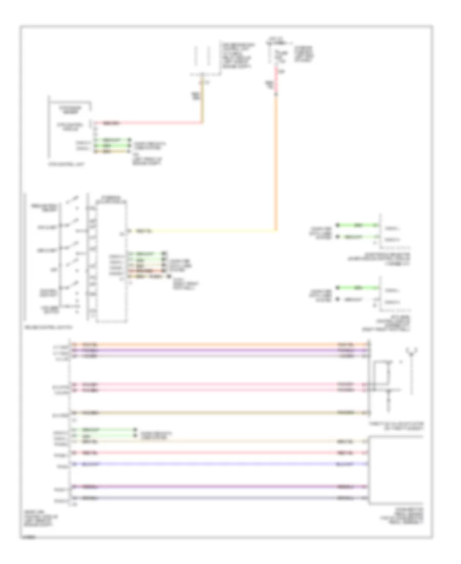
CRUISE CONTROL
Cruise Control Wiring Diagram for Mercedes-Benz CLS550 2010
List of elements for Cruise Control Wiring Diagram for Mercedes-Benz CLS550 2010:
- (7-speed a/t)
- A t dcm
- A t dcp
- A u up
- Acc & set
- Accelerator pedal sensor (top of accelerator pedal assembly)
- C29
- Can-b h
- Can-b l
- Can-c h
- Can-c l
- Computer data lines system
- Control contact
- Cruise control switch
- Dec & set
- Driver-side sam control unit w/ fuse & relay module (left side of engine compt)
- Dtr control module
- Dtr control unit
- Dtr radar sensor
- E a ip1s
- E a ip2s
- Electronic selector lever module control module
- Etc (egs) control module (5-speed a/t) (right front footwell)
- Fuse 7.5a
- Hot at all times
- I12
- Interior fuse box (left end of dash)
- M r ipm
- Me-sfi (me) control module (left rear of engine compt)
- Off
- Pwg+
- Pwg1-0
- Pwg1-1
- Pwg2-0
- Pwg2-1
- Resume from memory
- Steering column module
- Throttle valve actuator (on throttle body)
- Vcs (sbs) switch
- W15/1 (right front footwell)
- W9 (left front of engine compt)
 English