CRUISE CONTROL
Cruise Control Wiring Diagram for Mercedes-Benz GL350 2011
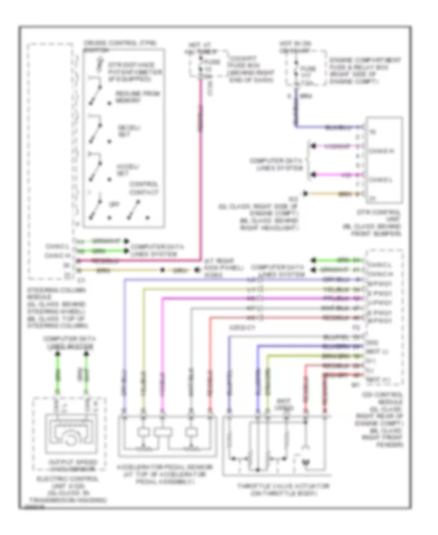
List of elements for Cruise Control Wiring Diagram for Mercedes-Benz GL350 2011:
- (+)
- (-)
- (at right kick panel) w29/2
- (not used)
- Accel/ set
- Accelerator pedal sensor (at top of accelerator pedal assembly)
- C h
- C13a
- Can
- Can c l
- Can-c h
- Can-c l
- Can-s h
- Can-s l
- Cdi control module (gl class: right rear of engine compt) (ml class: right front fender)
- Cockpit fuse box (behind right end of dash)
- Computer data lines system
- Contact
- Control
- Cruise control (tpm) switch
- Decel/ set
- Dtr control unit (ml class: behind front bumper)
- Dtr distance potentiometer (if equipped)
- E pwg1
- Electric control unit (vgs) (gl-class: in transmission housing)
- Engine compartment fuse & relay box (right side of engine compt)
- Fuse 5a
- Fuse 7.5a
- Hot at all times
- Hot in on or start
- M pwg1
- Mot (+)
- Mot (-)
- Mr4
- Off
- Output speed (vgs) sensor
- Resume from memory
- Sig
- Steering column module (gl class: behind steering wheel) (ml class: top of steering column)
- Throttle valve actuator (on throttle body)
- U pwg1
- W2 (gl class: right side of engine compt) (ml class: behind right headlight)
- X25/2-c1
 English