ELECTRONIC SUSPENSION
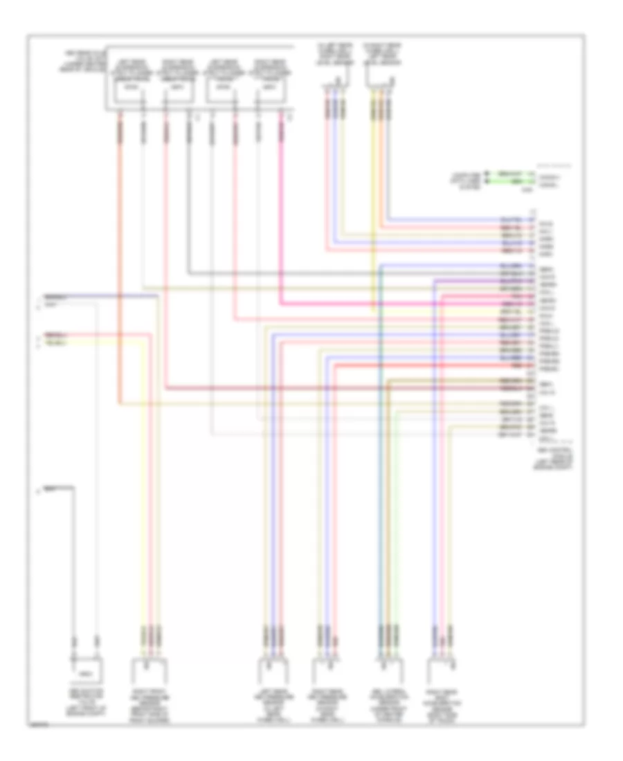
Active Body Control Wiring Diagram (1 of 2) for Mercedes-Benz S400 2011

List of elements for Active Body Control Wiring Diagram (1 of 2) for Mercedes-Benz S400 2011:
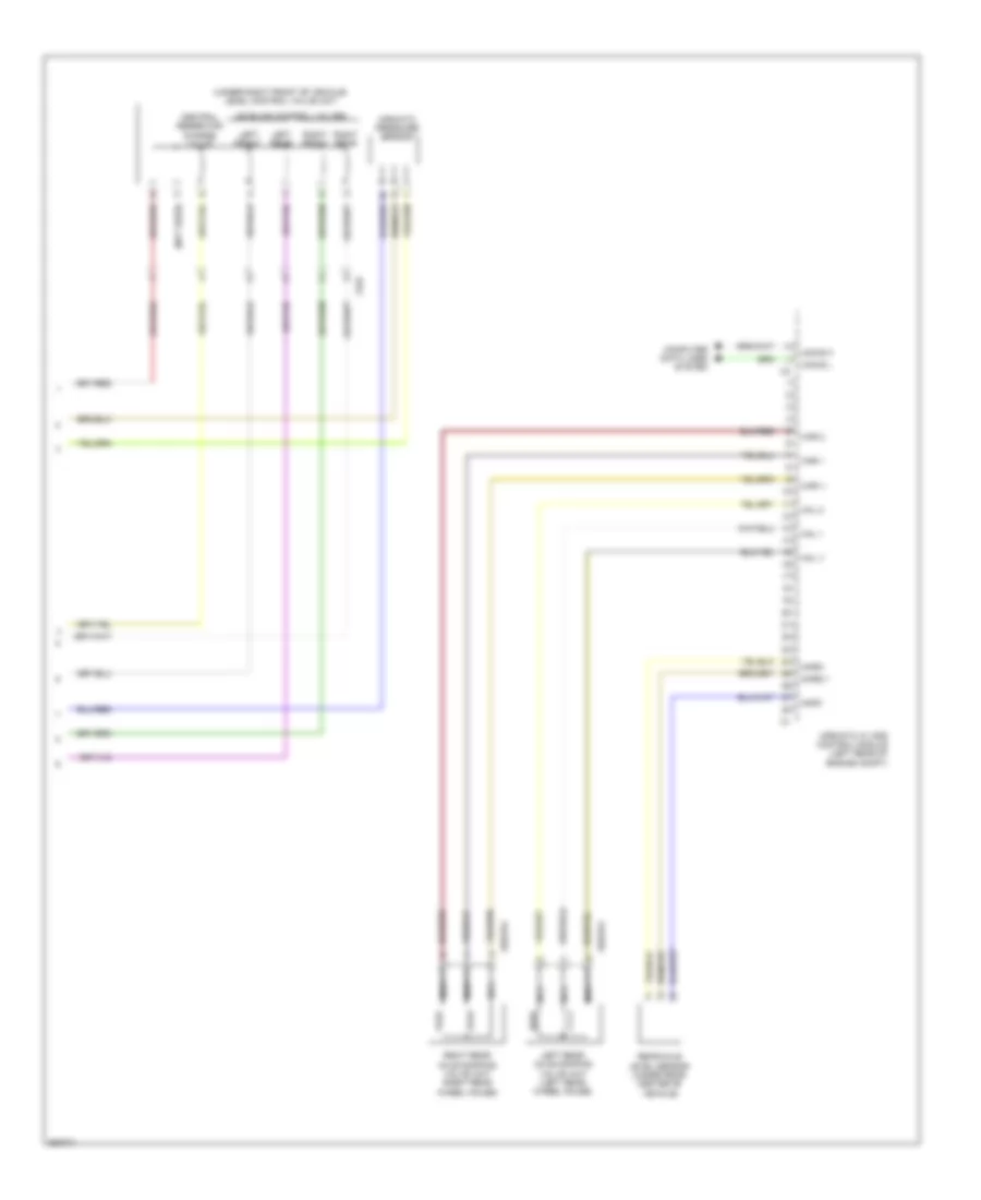
Active Body Control Wiring Diagram (2 of 2) for Mercedes-Benz S400 2011
List of elements for Active Body Control Wiring Diagram (2 of 2) for Mercedes-Benz S400 2011:
Airmatic Control Wiring Diagram (1 of 2) for Mercedes-Benz S400 2011
List of elements for Airmatic Control Wiring Diagram (1 of 2) for Mercedes-Benz S400 2011:
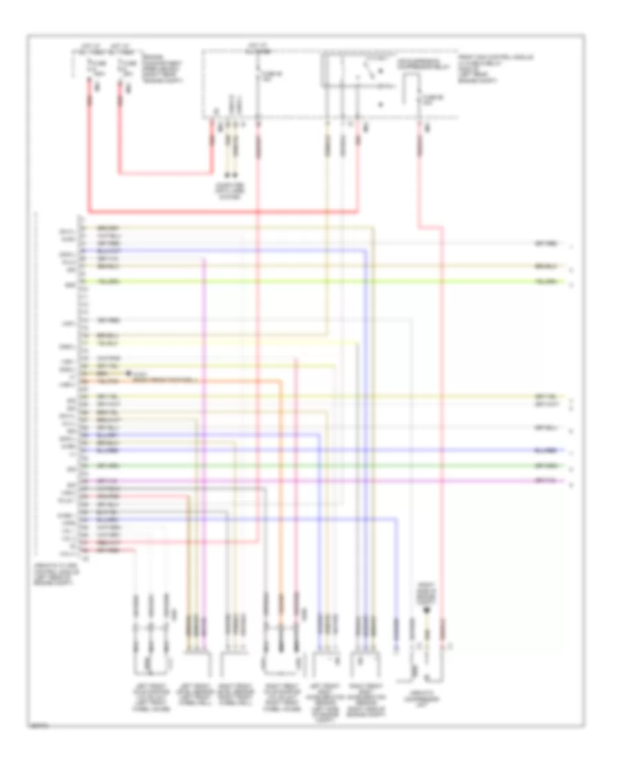
Airmatic Control Wiring Diagram (2 of 2) for Mercedes-Benz S400 2011
List of elements for Airmatic Control Wiring Diagram (2 of 2) for Mercedes-Benz S400 2011: