СИСТЕМА АНТИБЛОКИРОВОЧНОЙ ТОРМОЗНОЙ СИСТЕМЫ ABS
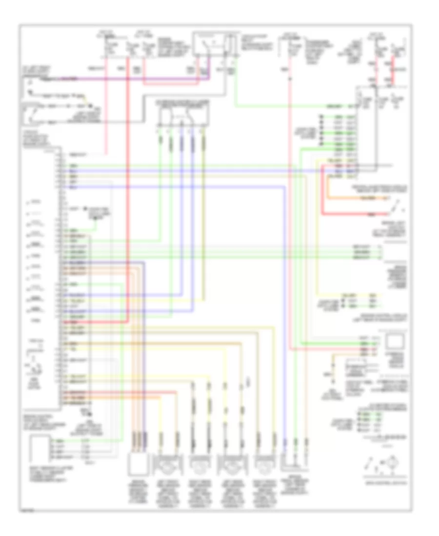
Электросхема антиблокировочной тормозной системы АБС (ABS), С Динамическое Управление Стабильностью для Volvo XC90 R-Design 2012
Электросхема антиблокировочной тормозной системы АБС (ABS), С Динамическое Управление Стабильностью для Volvo XC90 R-Design 2012 - Список элементов:
- (at left front of eng compt) vacuum pump
- (in center of dash) climate control module
- (on brake master cylinder) dstc activation unit
- 54/3.1
- 54/40d
- A10
- A11
- Abs pump motor
- B11
- B22
- B30
- B41
- B54
- Body sensor cluster stability sensor (under front passenger's seat)
- Brake control module (bcm) (at left rear corner of engine compt)
- Brake light contact (at top of brake pedal assembly)
- Brake pedal sensor (left rear corner of engine compt)
- Brake pressure sensor 1 (on brake master cylinder)
- Brake pressure sensor 2 (on brake master cylinder)
- C21
- C22
- C34
- C35
- Central electronic module (behind left side of dash)
- Computer data lines system
- Contact reel (top of steering column)
- D31
- D32
- D34
- D46
- D47
- D49
- Engine compartment distribution box (at left side of engine compt)
- Engine control module (left rear of engine compt)
- Fuse b1 30a
- Fuse b2 30a
- Fuse b21 20a
- Fuse c10 5a
- Fuse e4 50a
- Fuse e5 50a
- Fuse f15 5a
- Fuse f33 20a
- Fuse f9 5a
- G84 (at right kick panel)
- G93 (left side of engine compt, on strut tower)
- G95 (left side of engine compt,
- Hot at all times
- Left front abs sensor (behind left front wheel, on spindle hub assembly)
- Left rear abs sensor (behind left rear wheel, on spindle hub assembly)
- Main fuses (next to battery, in cargo compt)
- Nca
- On strut tower)
- Passenger compartment fuse box (at left end of dash)
- Red
- Right front abs sensor (behind right front wheel, on spindle hub assembly)
- Right rear abs sensor (behind right rear wheel, on spindle hub assembly)
- Spin control switch
- Steering angle sensor
- Steering angle sensor module
- Steering wheel module (swm) (in steering wheel)
- Vacuum pump relay (in engine compt relay/fuse box)
- Vacuum pump switch (at front of engine compt)
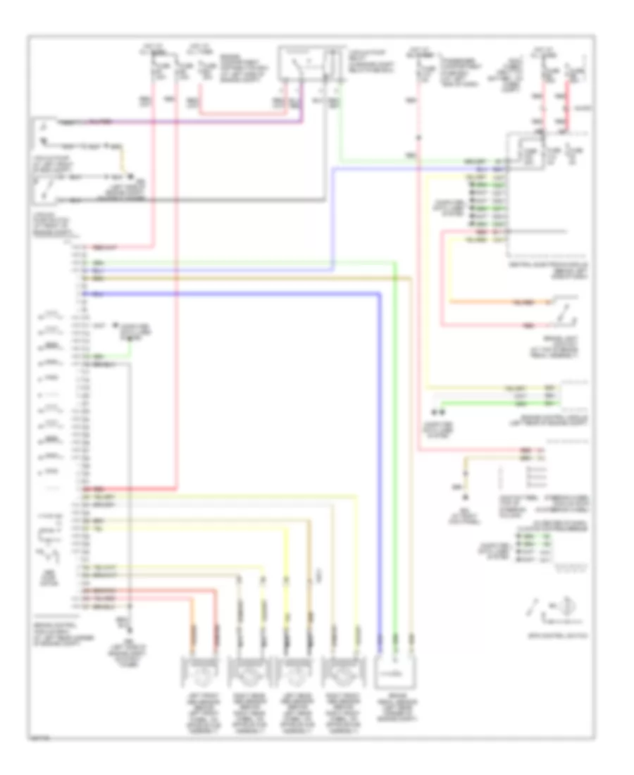
Электросхема антиблокировочной тормозной системы АБС (ABS), без Динамическое Управление Стабильностью для Volvo XC90 R-Design 2012
Электросхема антиблокировочной тормозной системы АБС (ABS), без Динамическое Управление Стабильностью для Volvo XC90 R-Design 2012 - Список элементов:
- (at left rear corner of engine compt)
- (in center of dash) climate control module
- 54/3.1
- 54/40d
- A10
- A11
- Abs pump motor
- B11
- B22
- B30
- B41
- B54
- Brake control
- Brake light contact (at top of brake pedal assembly)
- Brake pedal sensor (left rear corner of engine compt)
- C21
- C22
- C34
- C35
- Central electronic module (behind left side of dash)
- Computer data lines system
- Contact reel (top of steering column)
- D32
- D34
- D47
- D49
- Engine compartment distribution box (at left side of engine compt)
- Engine control module (left rear of engine compt)
- Fuse b1 30a
- Fuse b2 30a
- Fuse b21 20a
- Fuse c10 5a
- Fuse e4 50a
- Fuse e5 50a
- Fuse f15 5a
- Fuse f33 20a
- Fuse f9 5a
- G84 (at right kick panel)
- G93 (left side of engine compt, on strut tower)
- G95 (left side of engine compt, on strut tower)
- Hot at all times
- Left front abs sensor (behind left front wheel, on spindle hub assembly)
- Left rear abs sensor (behind left rear wheel, on spindle hub assembly)
- Main fuses (next to battery, in cargo compt)
- Module (bcm)
- Nca
- Passenger compartment fuse box (at left end of dash)
- Red
- Right front abs sensor (behind right front wheel, on spindle/hub assembly)
- Right rear abs sensor (behind right rear wheel, on spindle hub assembly)
- Spin control switch
- Steering wheel module (swm) (in steering wheel)
- Vacuum pump (at left front of eng compt)
- Vacuum pump relay (in engine compt relay/fuse box)
- Vacuum pump switch (at front of engine compt)

 Čeština
 Dansk
Dansk Deutsch
 Ελληνικά
 English
 Español
 Suomi
Suomi Français
 Français
 עברית
עברית Hrvatski
 Magyar
 Italiano
 日本語
日本語 한국어
한국어 Nederlands
 Polski
 Português
 Português
 Română
 Русский
 Slovenčina
 Slovenščina
 Svenska
 Türkçe
 中文 (中国)