ENGINE PERFORMANCE
3.5L
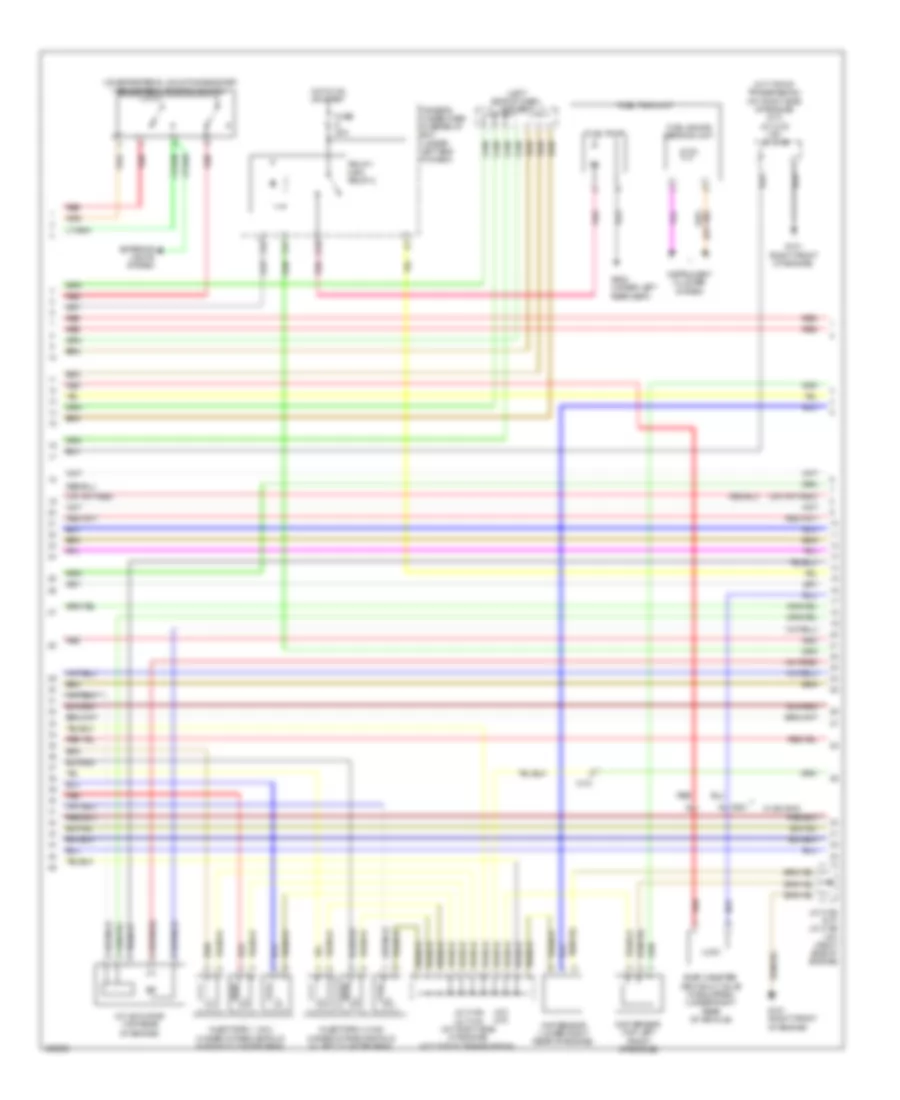
3.5L, Engine Performance Wiring Diagram (1 of 6) for Acura TL SH-AWD 2014

List of elements for 3.5L, Engine Performance Wiring Diagram (1 of 6) for Acura TL SH-AWD 2014:
- (left rear of engine compt) under-hood fuse/relay box
- (lower left rear of radiator)
- (on evap canister assembly) fuel tank pressure (ftp) sensor
- (top of accelerator pedal assembly) app sensor
- A/t
- A/t clutch pressure control solenoid valve b (left side of transmission housing, on secondary valve body)
- A/t clutch pressure control solenoid valve c (left side of transmission housing, on secondary valve body)
- A10
- A11
- A12
- A13
- A14
- A15
- A16
- A17
- A18
- A19
- A20
- A21
- A22
- A23
- A24
- A25
- A26
- A27
- A28
- A29
- A30
- A31
- A32
- A33
- A34
- A35
- A36
- A37
- A38
- A39
- A40
- A41
- A42
- A43
- A44
- A45
- A46
- A47
- A48
- A49
- Acc
- Air conditioning system
- Anti-theft system
- Apsa
- Apsb
- Atpp
- B10
- B11
- B12
- B13
- B14
- B15
- B16
- B17
- B18
- B19
- B20
- B21
- B22
- B23
- B24
- B25
- Barometer sensor
- Bksw
- Bkswnc
- C101
- C102
- C303
- C601
- Computer data lines system
- Computer data lines system electronic power steering system
- Cooling fans system
- Crmtcls
- Cruise control system
- Driver's under-dash fuse/relay box (under left end of dash)
- Ecm/pcm (right front of engine compt)
- Ect sensor 2
- Ect2
- Eld
- Eld unit
- Engine mount control solenoid valve (right rear of engine)
- Etcsrly
- F-can h
- F-can l
- F12
- F14
- Fanh
- Fanl
- Ftp
- Fuse 10a
- Fuse 15a
- Fuse 20a
- G101 (right front of engine)
- G301 (behind left end of front bumper)
- Hot at all times
- Hot in on or start
- Iat sensor
- Igp
- Igpls3
- Igpls4
- Igpls5
- Igpls6
- Imofpr
- Imtm
- Inj1
- Inj2
- Inj3
- Inj4
- Inj5
- Inj6
- J/c c106 (right side of engine)
- J/c c107 (a/t) j/c c103 (m/t) (a/t: right side of engine) (m/t: top of transmission)
- Lg3
- Lsb
- Lsc
- M/t
- Maf sensor
- Maf/iat sensor (on intake air filter housing)
- Mcs
- Mrly
- Mtclsw
- Navigation system
- Nep
- Pg2
- Pnk
- Power distribution system
- Red
- Rvs
- S net
- Scs
- Sdnp
- Sg3
- Sg4
- Sh02sb1
- Shift interlock system
- Sho2sb2
- Sls
- Starting/ charging system
- Starting/charging system
- Strld
- Strly
- Sts
- Subrly
- Supp
- Tpsa
- Under-hood fuse/relay box (left rear of of engine compt)
- Vbsol1
- Vbsol2
- Vbum
- Vcc3
- Vcc4
- Vcc5
- Vcentb1
- Vcentb2
- Vg+
- Vg-
- Vsb1
- Vsb2
- Vsp
- Vsv
- Vtpsw
- W/ sh-awd
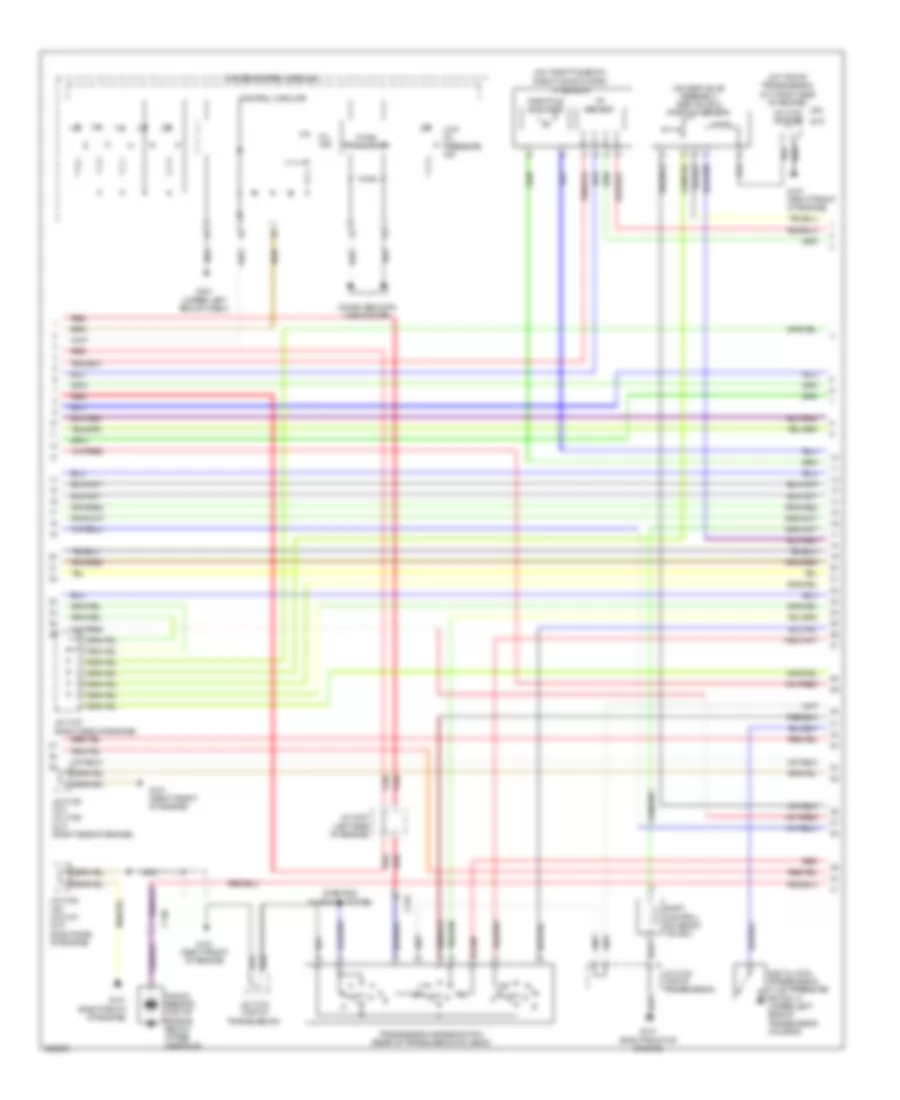
3.5L, Engine Performance Wiring Diagram (2 of 6) for Acura TL SH-AWD 2014
List of elements for 3.5L, Engine Performance Wiring Diagram (2 of 6) for Acura TL SH-AWD 2014:
- (a/t) (m/t)
- (left side of dash) j/c c307
- (m/t: top of transmission) (a/t: right side of engine) (m/t) j/c c103 (a/t) j/c c106
- (on brake pedal mounting bracket) brake pedal position switch
- (right front of engine)
- C101
- C601
- Ckp sensor (lower right rear of engine)
- Cmp sensor (top left front of engine)
- D10
- Driver's under-dash fuse/relay box (under left end of dash)
- Evap canister vent shut valve (if equipped) (under right rear of vehicle)
- Exterior lights system
- F22
- F31
- Fuel gauge sending unit
- Fuel pump
- Fuel tank unit
- Fuse 20a
- G101
- G101 (right front of engine)
- G602 (under left rear seat)
- Hot in on or start
- Imt actuator (top rear of engine)
- Injectors 1, 2 & 3 (under intake manifold in right cylinder bank)
- Injectors 4, 5 & 6 (under intake manifold in left cylinder bank)
- Instrument cluster system
- J/c c105 (m/t) j/c c106 (a/t) (right side of engine)
- J/c c106 j/c c103 (a/t: right side of engine) (m/t: top of transmission)
- Pgm-f1 main relay 2
- Pnk
- Red
- W/ sh-awd
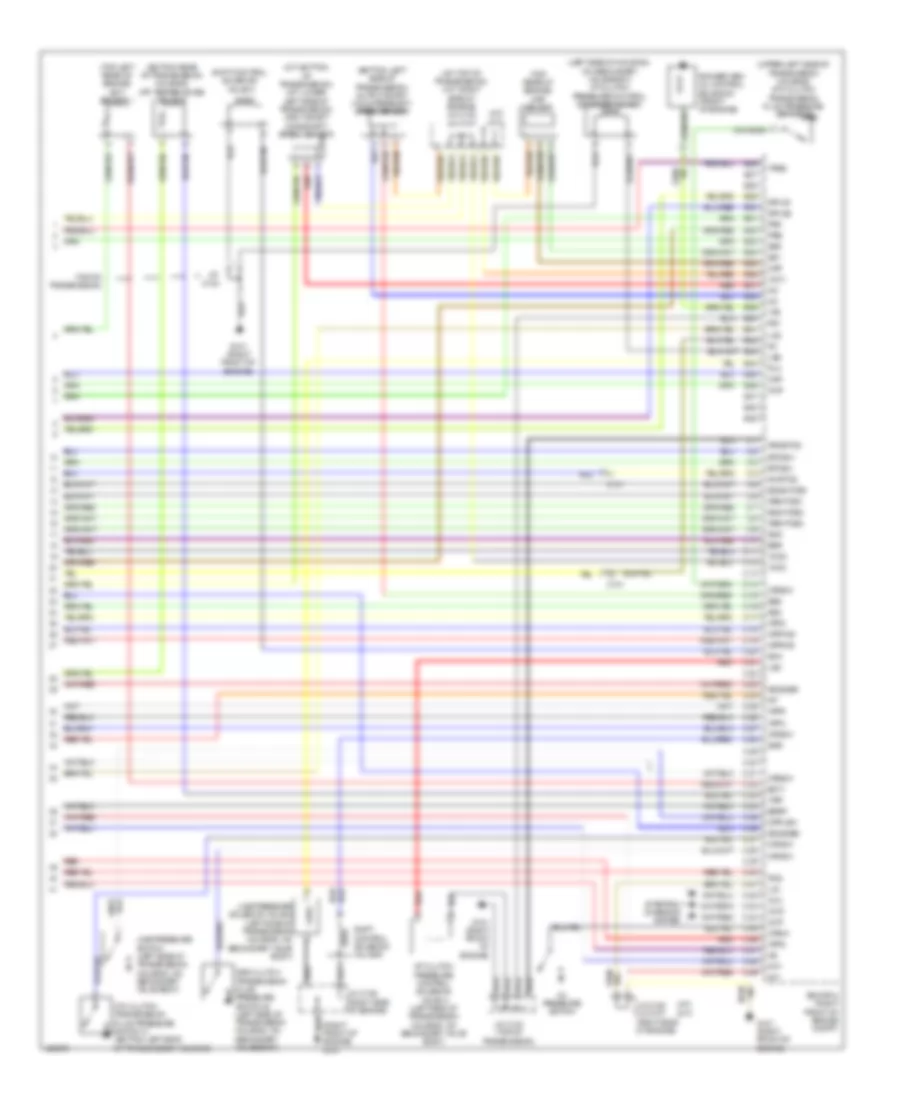
3.5L, Engine Performance Wiring Diagram (3 of 6) for Acura TL SH-AWD 2014
List of elements for 3.5L, Engine Performance Wiring Diagram (3 of 6) for Acura TL SH-AWD 2014:
- (a/t)
- (in left exhaust manifold)
- (in left exhaust, downstream of catalytic converter) front secondary ho2s (b2, s2)
- (in right exhaust manifold) rear a/f sensor (b1, s1)
- (in right exhaust, downstream of catalytic converter)
- (m/t)
- (right front of engine) g101
- (right side of engine) (m/t) j/c c106 (a/t) j/c c107
- (right side of engine) (m/t) j/c c107 (a/t) j/c c105
- 6th clutch transmission fluid pressure switch e (left side of transmission housing, on secondary valve body)
- A15
- A17
- C101
- C12
- C15
- C17
- C306
- Cable reel (in steering column)
- Cruise control combination select/reset/information switch
- Evap canister purge valve (right rear of engine)
- Front a/f sensor (b2, s1)
- Fuse 10a
- G101 (right front of engine)
- G401 (upper left end of dash)
- G405 (right end of dash)
- Hot at all times
- J/c c107 (m/t) j/c c105 (a/t) (right side of engine)
- Nca
- Paddle shifter (downshift
- Paddle shifter+ (upshift
- Rear secondary ho2s (b1, s2)
- Red
- Rocker arm oil pressure switch (front of engine)
- Steering wheel
- Switch) 1) shift down
- Switch) 1) shift up
- Under-hood fuse/relay box (left rear of engine compt)
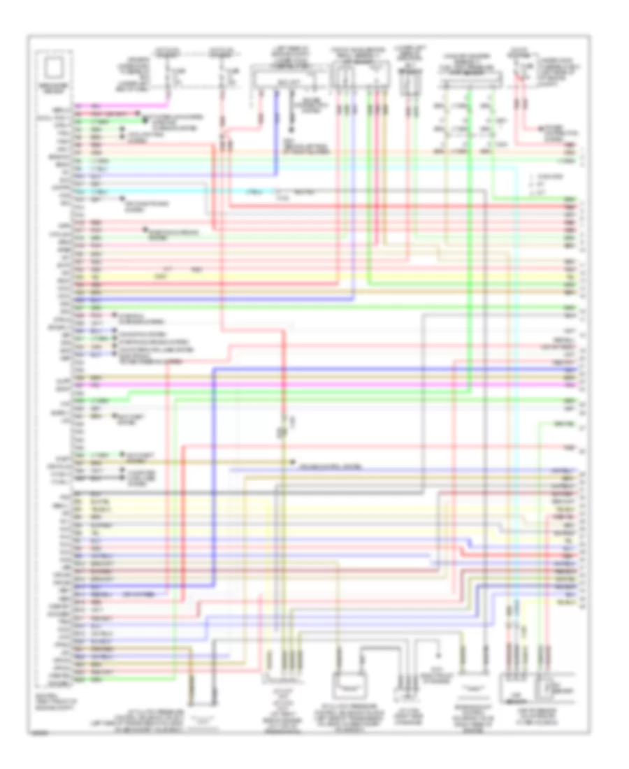
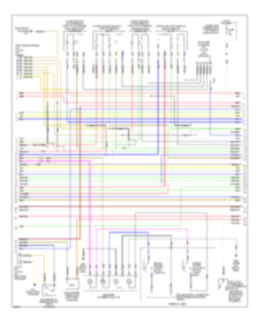
3.5L, Engine Performance Wiring Diagram (4 of 6) for Acura TL SH-AWD 2014
List of elements for 3.5L, Engine Performance Wiring Diagram (4 of 6) for Acura TL SH-AWD 2014:
- (right side of engine)
- (top of left cylinder bank)
- (top of right cylinder bank)
- A16
- Air conditioning system
- Atp-d
- B26
- C101
- C303
- C306
- C404
- C701
- Driver's junction box 1 (behind right side of instrument cluster)
- Driver's misc
- Driver's under-dash fuse/relay box (under left end of dash)
- E10
- Etcs control relay
- Fuse 15a
- Fuse 7.5a
- G101 (right front of engine)
- Hot at all times
- Hot in on or start
- Icm
- Ignition coil 1
- Ignition coil 2
- Ignition coil 3
- Ignition coil 4
- Ignition coil 5
- Ignition coil 6
- Ignition coil relay
- J/c c103 (a/t) j/c c106 (m/t) (a/t: top of transmission) (m/t: right side of engine)
- J/c c106 (a/t) j/c c103 (m/t) (a/t: right side of engine) (m/t: top of transmission)
- J/c c107 (a/t) j/c c106 (m/t)
- P20
- Pgm-fi main relay 1
- Pgm-fi sub-relay
- Power control unit (w/ keyless access) (left end of dash)
- Power seat control unit (under driver's seat)
- Red
- Under-hood fuse/relay box (left rear of engine compt)
- W/ ventilated seats
- W/o ventilated seats
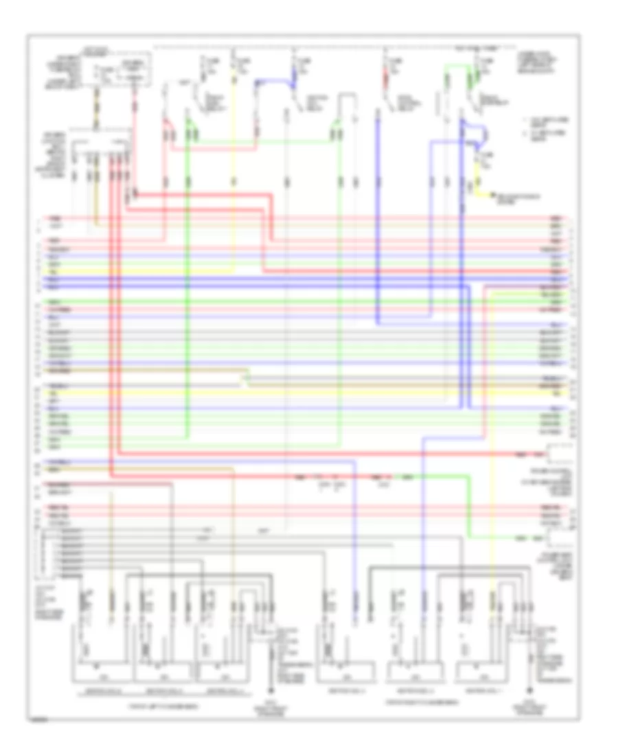
3.5L, Engine Performance Wiring Diagram (5 of 6) for Acura TL SH-AWD 2014
List of elements for 3.5L, Engine Performance Wiring Diagram (5 of 6) for Acura TL SH-AWD 2014:
- (a/t)
- (a/t: top of transmission) (m/t: right side of engine)
- (m/t)
- (on egr valve assembly) egr valve & position sensor
- (on throttle body) throttle actuator/
- 2nd clutch transmission fluid pressure switch a (upper left side of transmission housing)
- C101
- C104
- Computer data lines system
- Control circuits
- F-can transceiver
- G101 (right front of engine)
- G401 (upper left end of dash)
- Gauge control module
- J/c c103 (top of transmission)
- J/c c103 j/c c106
- J/c c105 (a/t) j/c c106 (m/t) (right side of engine)
- J/c c105 (a/t) j/c c107 (m/t) (right side of engine)
- J/c c107 (right side of engine)
- J/c c307 (left side of engine)
- Knock sensor (top of engine, below intake manifold)
- Low oil pressure ind
- Mil ind
- N r
- Nca
- Red
- Shift control solenoid valve c
- Starting/ charging system
- Throttle actuator
- Tp sensor
- Transmission range switch (rear of transmission housing)
3.5L, Engine Performance Wiring Diagram (6 of 6) for Acura TL SH-AWD 2014
List of elements for 3.5L, Engine Performance Wiring Diagram (6 of 6) for Acura TL SH-AWD 2014:
- (a/t)
- (a/t: top of transmission) (m/t: right side of engine) j/c c103 j/c c107
- (bottom left side of transmission) output shaft (countershaft) speed sensor
- (bottom rear of transmission housing) atf temperature sensor
- (left side of housing, on secondary valve body) a/t clutch pressure control solenoid valve d
- (m/t)
- (m/t: bottom of transmission) (a/t: lower left side of transmission) input shaft (mainshaft) speed sensor
- (top left rear of engine) ect sensor 1
- (top of transmission)
- (top rear of engine) map sensor
- (upper left side of transmission housing) 5th clutch transmission fluid pressure switch d
- 3rd clutch transmission fluid pressure switch b (left side of transmission housing, on secondary valve body)
- 4th clutch transmission fluid pressure switch c (bottom left side of transmission housing)
- A/t clutch pressure control solenoid valve a (left side of transmission housing, on secondary valve body)
- Afshtcb1
- Afshtcb2
- Altc
- Altf
- Altl
- Atpd
- Atpfwd
- Atpn
- Atpr
- Atprvs
- Atps
- B26
- B27
- B28
- B29
- B30
- B31
- B32
- B33
- B34
- B35
- B36
- B37
- B38
- B39
- B40
- B41
- B42
- B43
- B44
- B45
- B46
- B47
- B48
- B49
- C10
- C101
- C11
- C12
- C13
- C14
- C15
- C16
- C17
- C18
- C19
- C20
- C21
- C22
- C23
- C24
- C25
- C26
- C27
- C28
- C29
- C30
- C31
- C32
- C33
- C34
- C35
- C36
- C37
- C38
- C39
- C40
- C41
- C42
- C43
- C44
- C45
- C46
- C47
- C48
- C49
- Ckp
- Cmp
- Ecm/pcm (right front of engine compt)
- Ect1
- Egr
- Egrp
- Engine) g101
- Etcsm+
- Etcsm-
- G101 (right front of engine)
- Iat
- Ig1
- Ig1etcs
- Igpls1
- Igpls2
- Imt+
- Imt-
- Ipb1
- Ipb2
- J/c c103
- J/c c103 (top of transmission)
- J/c c105 j/c c107 (right side of engine)
- J/c c106 (right side of engine)
- Lg1
- Lg2
- Line pressure solenoid valve a (left side of transmission housing, on secondary valve body)
- Line pressure switch (left side of transmission housing, on secondary valve body)
- Lsa
- Lsd
- Map
- Oil pressure switch
- Op2sw
- Op3sw
- Op4sw
- Op5sw
- Op6sw
- Opsw
- Pcs
- Pg1
- Pgmetcs
- Pla
- Red
- Rocker arm oil control solenoid (front of engine)
- S02htcb2
- S02shtcb1
- Sg1
- Sg2
- Sg5
- Sg6
- Sha
- Shb
- Shd
- Shift control solenoid valve a
- Shift control solenoid volve b
- So2sgb1
- So2sgb2
- Starting/ charging system
- Tatf
- Tpsb
- Vcc1
- Vcc2
- Vcc6
- Vts
3.7L
3.7L, Engine Performance Wiring Diagram (1 of 6) for Acura TL SH-AWD 2014
List of elements for 3.7L, Engine Performance Wiring Diagram (1 of 6) for Acura TL SH-AWD 2014:
- (left rear of engine compt) under-hood fuse/relay box
- (lower left rear of radiator)
- (on evap canister assembly) fuel tank pressure (ftp) sensor
- (top of accelerator pedal assembly) app sensor
- A/t
- A/t clutch pressure control solenoid valve b (left side of transmission housing, on secondary valve body)
- A/t clutch pressure control solenoid valve c (left side of transmission housing, on secondary valve body)
- A10
- A11
- A12
- A13
- A14
- A15
- A16
- A17
- A18
- A19
- A20
- A21
- A22
- A23
- A24
- A25
- A26
- A27
- A28
- A29
- A30
- A31
- A32
- A33
- A34
- A35
- A36
- A37
- A38
- A39
- A40
- A41
- A42
- A43
- A44
- A45
- A46
- A47
- A48
- A49
- Acc
- Air conditioning system
- Anti-theft system
- Apsa
- Apsb
- Atpp
- B10
- B11
- B12
- B13
- B14
- B15
- B16
- B17
- B18
- B19
- B20
- B21
- B22
- B23
- B24
- B25
- Barometer sensor
- Bksw
- Bkswnc
- C101
- C102
- C303
- C601
- Computer data lines system
- Computer data lines system electronic power steering system
- Cooling fans system
- Crmtcls
- Cruise control system
- Driver's under-dash fuse/relay box (under left end of dash)
- Ecm/pcm (right front of engine compt)
- Ect sensor 2
- Ect2
- Eld
- Eld unit
- Engine mount control solenoid valve (right rear of engine)
- Etcsrly
- F-can h
- F-can l
- F12
- F14
- Fanh
- Fanl
- Ftp
- Fuse 10a
- Fuse 15a
- Fuse 20a
- G101 (right front of engine)
- G301 (behind left end of front bumper)
- Hot at all times
- Hot in on or start
- Iat sensor
- Igp
- Igpls3
- Igpls4
- Igpls5
- Igpls6
- Imofpr
- Imtm
- Inj1
- Inj2
- Inj3
- Inj4
- Inj5
- Inj6
- J/c c106 (right side of engine)
- J/c c107 (a/t) j/c c103 (m/t) (a/t: right side of engine) (m/t: top of transmission)
- Lg3
- Lsb
- Lsc
- M/t
- Maf sensor
- Maf/iat sensor (on intake air filter housing)
- Mcs
- Mrly
- Mtclsw
- Navigation system
- Nep
- Pg2
- Pnk
- Power distribution system
- Red
- Rvs
- S net
- Scs
- Sdnp
- Sg3
- Sg4
- Sh02sb1
- Shift interlock system
- Sho2sb2
- Sls
- Starting/ charging system
- Starting/charging system
- Strld
- Strly
- Sts
- Subrly
- Supp
- Tpsa
- Under-hood fuse/relay box (left rear of of engine compt)
- Vbsol1
- Vbsol2
- Vbum
- Vcc3
- Vcc4
- Vcc5
- Vcentb1
- Vcentb2
- Vg+
- Vg-
- Vsb1
- Vsb2
- Vsp
- Vsv
- Vtpsw
- W/ sh-awd
3.7L, Engine Performance Wiring Diagram (2 of 6) for Acura TL SH-AWD 2014
List of elements for 3.7L, Engine Performance Wiring Diagram (2 of 6) for Acura TL SH-AWD 2014:
- (a/t) (m/t)
- (left side of dash) j/c c307
- (m/t: top of transmission) (a/t: right side of engine) (m/t) j/c c103 (a/t) j/c c106
- (on brake pedal mounting bracket) brake pedal position switch
- (right front of engine)
- C101
- C601
- Ckp sensor (lower right rear of engine)
- Cmp sensor (top left front of engine)
- D10
- Driver's under-dash fuse/relay box (under left end of dash)
- Evap canister vent shut valve (if equipped) (under right rear of vehicle)
- Exterior lights system
- F22
- F31
- Fuel gauge sending unit
- Fuel pump
- Fuel tank unit
- Fuse 20a
- G101
- G101 (right front of engine)
- G602 (under left rear seat)
- Hot in on or start
- Imt actuator (top rear of engine)
- Injectors 1, 2 & 3 (under intake manifold in right cylinder bank)
- Injectors 4, 5 & 6 (under intake manifold in left cylinder bank)
- Instrument cluster system
- J/c c105 (m/t) j/c c106 (a/t) (right side of engine)
- J/c c106 j/c c103 (a/t: right side of engine) (m/t: top of transmission)
- Pgm-f1 main relay 2
- Pnk
- Red
- W/ sh-awd
3.7L, Engine Performance Wiring Diagram (3 of 6) for Acura TL SH-AWD 2014
List of elements for 3.7L, Engine Performance Wiring Diagram (3 of 6) for Acura TL SH-AWD 2014:
- (a/t)
- (in left exhaust manifold)
- (in left exhaust, downstream of catalytic converter) front secondary ho2s (b2, s2)
- (in right exhaust manifold) rear a/f sensor (b1, s1)
- (in right exhaust, downstream of catalytic converter)
- (m/t)
- (right front of engine) g101
- (right side of engine) (m/t) j/c c106 (a/t) j/c c107
- (right side of engine) (m/t) j/c c107 (a/t) j/c c105
- 6th clutch transmission fluid pressure switch e (left side of transmission housing, on secondary valve body)
- A15
- A17
- C101
- C12
- C15
- C17
- C306
- Cable reel (in steering column)
- Cruise control combination select/reset/information switch
- Evap canister purge valve (right rear of engine)
- Front a/f sensor (b2, s1)
- Fuse 10a
- G101 (right front of engine)
- G401 (upper left end of dash)
- G405 (right end of dash)
- Hot at all times
- J/c c107 (m/t) j/c c105 (a/t) (right side of engine)
- Nca
- Paddle shifter (downshift
- Paddle shifter+ (upshift
- Rear secondary ho2s (b1, s2)
- Red
- Rocker arm oil pressure switch (front of engine)
- Steering wheel
- Switch) 1) shift down
- Switch) 1) shift up
- Under-hood fuse/relay box (left rear of engine compt)
3.7L, Engine Performance Wiring Diagram (4 of 6) for Acura TL SH-AWD 2014
List of elements for 3.7L, Engine Performance Wiring Diagram (4 of 6) for Acura TL SH-AWD 2014:
- (right side of engine)
- (top of left cylinder bank)
- (top of right cylinder bank)
- A16
- Air conditioning system
- Atp-d
- B26
- C101
- C303
- C306
- C404
- C701
- Driver's junction box 1 (behind right side of instrument cluster)
- Driver's misc
- Driver's under-dash fuse/relay box (under left end of dash)
- E10
- Etcs control relay
- Fuse 15a
- Fuse 7.5a
- G101 (right front of engine)
- Hot at all times
- Hot in on or start
- Icm
- Ignition coil 1
- Ignition coil 2
- Ignition coil 3
- Ignition coil 4
- Ignition coil 5
- Ignition coil 6
- Ignition coil relay
- J/c c103 (a/t) j/c c106 (m/t) (a/t: top of transmission) (m/t: right side of engine)
- J/c c106 (a/t) j/c c103 (m/t) (a/t: right side of engine) (m/t: top of transmission)
- J/c c107 (a/t) j/c c106 (m/t)
- P20
- Pgm-fi main relay 1
- Pgm-fi sub-relay
- Power control unit (w/ keyless access) (left end of dash)
- Power seat control unit (under driver's seat)
- Red
- Under-hood fuse/relay box (left rear of engine compt)
- W/ ventilated seats
- W/o ventilated seats
3.7L, Engine Performance Wiring Diagram (5 of 6) for Acura TL SH-AWD 2014
List of elements for 3.7L, Engine Performance Wiring Diagram (5 of 6) for Acura TL SH-AWD 2014:
- (a/t)
- (a/t: top of transmission) (m/t: right side of engine)
- (m/t)
- (on egr valve assembly) egr valve & position sensor
- (on throttle body) throttle actuator/
- 2nd clutch transmission fluid pressure switch a (upper left side of transmission housing)
- C101
- C104
- Computer data lines system
- Control circuits
- F-can transceiver
- G101 (right front of engine)
- G401 (upper left end of dash)
- Gauge control module
- J/c c103 (top of transmission)
- J/c c103 j/c c106
- J/c c105 (a/t) j/c c106 (m/t) (right side of engine)
- J/c c105 (a/t) j/c c107 (m/t) (right side of engine)
- J/c c107 (right side of engine)
- J/c c307 (left side of engine)
- Knock sensor (top of engine, below intake manifold)
- Low oil pressure ind
- Mil ind
- N r
- Nca
- Red
- Shift control solenoid valve c
- Starting/ charging system
- Throttle actuator
- Tp sensor
- Transmission range switch (rear of transmission housing)
3.7L, Engine Performance Wiring Diagram (6 of 6) for Acura TL SH-AWD 2014
List of elements for 3.7L, Engine Performance Wiring Diagram (6 of 6) for Acura TL SH-AWD 2014:
- (a/t)
- (a/t: top of transmission) (m/t: right side of engine) j/c c103 j/c c107
- (bottom left side of transmission) output shaft (countershaft) speed sensor
- (bottom rear of transmission housing) atf temperature sensor
- (left side of housing, on secondary valve body) a/t clutch pressure control solenoid valve d
- (m/t)
- (m/t: bottom of transmission) (a/t: lower left side of transmission) input shaft (mainshaft) speed sensor
- (top left rear of engine) ect sensor 1
- (top of transmission)
- (top rear of engine) map sensor
- (upper left side of transmission housing) 5th clutch transmission fluid pressure switch d
- 3rd clutch transmission fluid pressure switch b (left side of transmission housing, on secondary valve body)
- 4th clutch transmission fluid pressure switch c (bottom left side of transmission housing)
- A/t clutch pressure control solenoid valve a (left side of transmission housing, on secondary valve body)
- Afshtcb1
- Afshtcb2
- Altc
- Altf
- Altl
- Atpd
- Atpfwd
- Atpn
- Atpr
- Atprvs
- Atps
- B26
- B27
- B28
- B29
- B30
- B31
- B32
- B33
- B34
- B35
- B36
- B37
- B38
- B39
- B40
- B41
- B42
- B43
- B44
- B45
- B46
- B47
- B48
- B49
- C10
- C101
- C11
- C12
- C13
- C14
- C15
- C16
- C17
- C18
- C19
- C20
- C21
- C22
- C23
- C24
- C25
- C26
- C27
- C28
- C29
- C30
- C31
- C32
- C33
- C34
- C35
- C36
- C37
- C38
- C39
- C40
- C41
- C42
- C43
- C44
- C45
- C46
- C47
- C48
- C49
- Ckp
- Cmp
- Ecm/pcm (right front of engine compt)
- Ect1
- Egr
- Egrp
- Engine) g101
- Etcsm+
- Etcsm-
- G101 (right front of engine)
- Iat
- Ig1
- Ig1etcs
- Igpls1
- Igpls2
- Imt+
- Imt-
- Ipb1
- Ipb2
- J/c c103
- J/c c103 (top of transmission)
- J/c c105 j/c c107 (right side of engine)
- J/c c106 (right side of engine)
- Lg1
- Lg2
- Line pressure solenoid valve a (left side of transmission housing, on secondary valve body)
- Line pressure switch (left side of transmission housing, on secondary valve body)
- Lsa
- Lsd
- Map
- Oil pressure switch
- Op2sw
- Op3sw
- Op4sw
- Op5sw
- Op6sw
- Opsw
- Pcs
- Pg1
- Pgmetcs
- Pla
- Red
- Rocker arm oil control solenoid (front of engine)
- S02htcb2
- S02shtcb1
- Sg1
- Sg2
- Sg5
- Sg6
- Sha
- Shb
- Shd
- Shift control solenoid valve a
- Shift control solenoid volve b
- So2sgb1
- So2sgb2
- Starting/ charging system
- Tatf
- Tpsb
- Vcc1
- Vcc2
- Vcc6
- Vts