ENGINE PERFORMANCE
2.4L
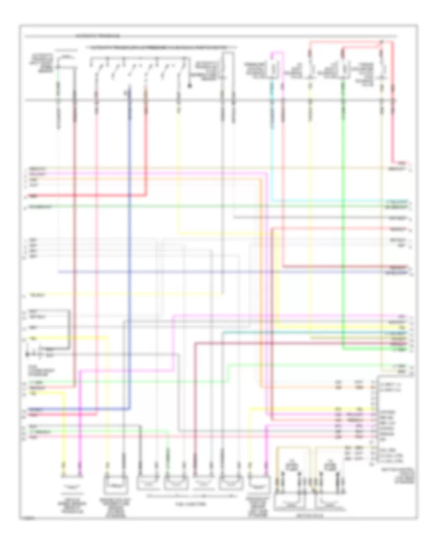
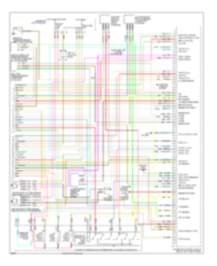
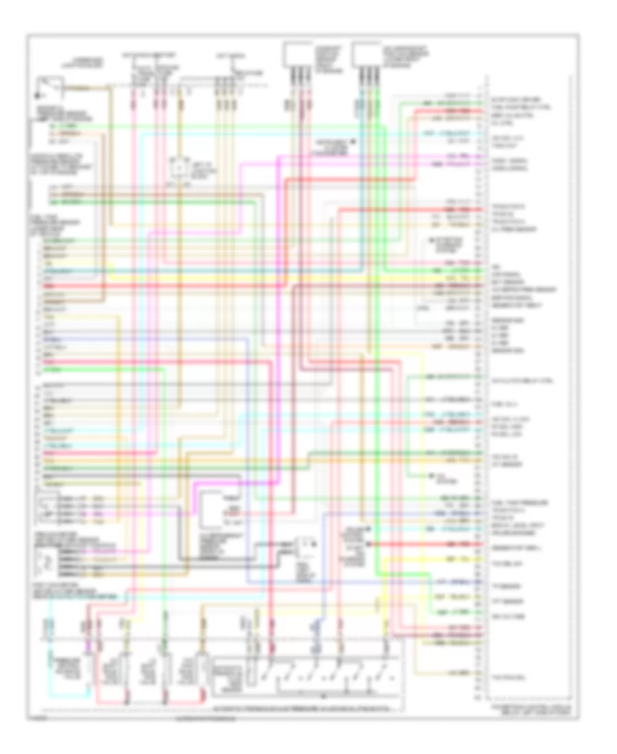
2.4L VIN T, Engine Performance Wiring Diagrams (1 of 3) for Chevrolet Malibu LS 1999

List of elements for 2.4L VIN T, Engine Performance Wiring Diagrams (1 of 3) for Chevrolet Malibu LS 1999:
- 5v ref
- A/c pres
- A/c refrigerant pressure sensor (front of engine compt)
- A/t iss sens
- All times
- B12
- Battery
- Ckp ref
- Cmp sens
- Cruise control brake switch (on brake pedal support)
- Cruise fuse 10a
- Data link connector (left side of dash)
- Ect sensor
- Engine oil pressure sensor (top rear of engine)
- F/p injr fuse 15a
- Fuel pump
- Fuel pump relay
- Fuel tank module
- Fuel tank pres
- Fuel tank pressure sensor (under rear of vehicle)
- G125 (lower front of engine)
- G300 (below left front seat)
- Gen term f
- Gen term l
- Generator
- Hot at
- Hot in acc, run or start
- Hot in run
- Hot in run or start
- Ign
- Ign ctrl 1-4
- Ign ctrl 2-3
- Ign mod fuse 10a
- Inj 1
- Inj 2
- Knock sensor (right rear of engine)
- Ks signal
- Left i/p junction block
- Map sensor
- Oil pres
- Pcm batt fuse 10a
- Pcm acc fuse 10a
- Pcm gnd
- Pcm ground
- Pcm ign fuse 10a
- Pnk
- Powertrain control module (below left side of dash)
- Red
- Right i/p junction block
- Serial data
- Tcc bk sw
- Tft sensor
- Throttle position sensor (left side of engine)
- Tp sensor
- Tr sw a
- Tr sw input b
- Tr sw input c
- Tr sw input p
- Transaxle range switch
- Tx range a
- Tx range b
- Tx range c
- Underhood junction block
- Vss high
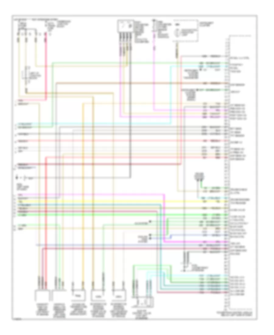
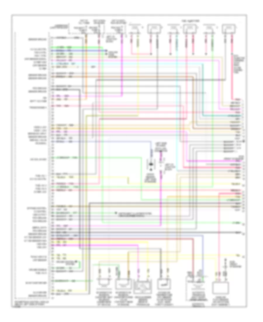
2.4L VIN T, Engine Performance Wiring Diagrams (2 of 3) for Chevrolet Malibu LS 1999
List of elements for 2.4L VIN T, Engine Performance Wiring Diagrams (2 of 3) for Chevrolet Malibu LS 1999:
- 1-2 shift solenoid valve
- 1-4 coil ctrl
- 2-3 coil ctrl
- 2-3 shift solenoid valve
- Automatic transaxle
- Automatic transaxle fluid pressure valve manual position switch
- Automatic transaxle fluid temperature sensor
- Automatic transaxle input shaft speed sensor
- Ckp gnd
- Ckp sig
- Coil pos
- Crankshaft position sensor (left side of engine)
- Engine coolant temperature sensor (on rear of engine)
- Fuel injectors
- G125 (lower front of engine)
- Ground
- Ic input 1-4
- Ic input 2-3
- Ign
- Ignition coils
- Ignition control module (top rear of engine)
- Nca
- Pnk
- Pressure control solenoid valve
- Red
- Ref low
- Ref sig
- Tan
- To spark plugs
- Torque converter clutch pwm solenoid valve
- Vehicle speed sensor (rear of transaxle)
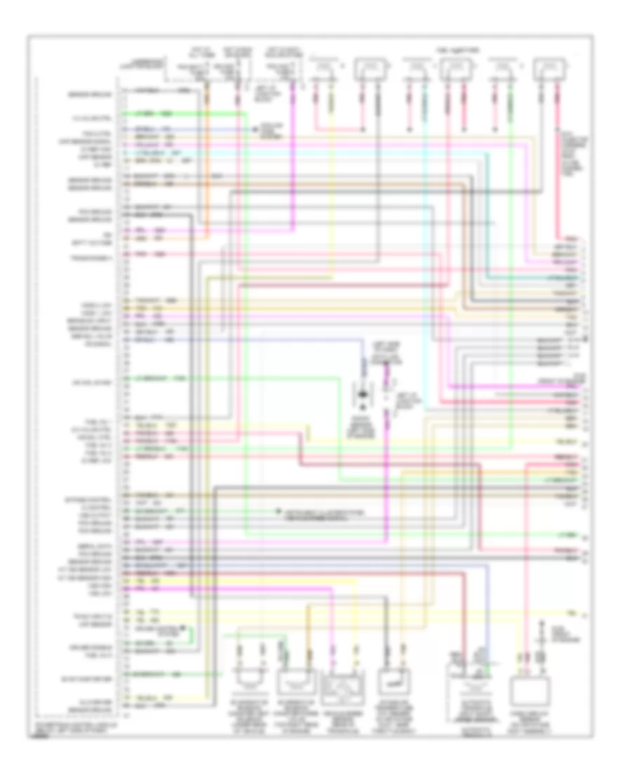
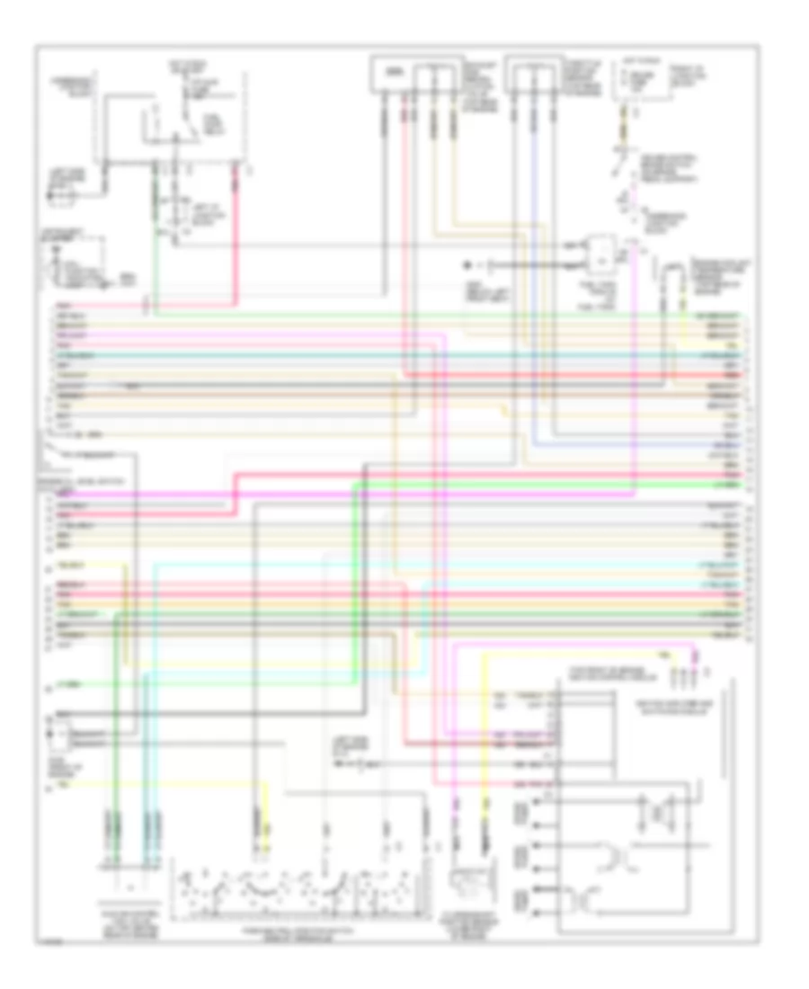
2.4L VIN T, Engine Performance Wiring Diagrams (3 of 3) for Chevrolet Malibu LS 1999
List of elements for 2.4L VIN T, Engine Performance Wiring Diagrams (3 of 3) for Chevrolet Malibu LS 1999:
- 1-2 ss valve
- 2-3 ss valve
- A/ pres +5v
- A/c clutch rly
- A/c system
- A/t iss sens
- Auto trans fuse 10a
- B11
- C11
- Camshaft position sensor (top front of engine)
- Cmp sens b+
- Cmp sens gnd
- Cooling fans system
- Cruise control system
- Cruise diable
- Cruise engaged
- Ect sens
- Erls fuse 10a
- Evap can vnt
- Evap canp
- Evaporative emission canister purge valve (left front of engine)
- Evaporative emission canister vent solenoid (under rear of vehicle)
- F pump rly
- G125 (lower front of engine)
- G202 (left side of dash)
- Hot in run
- Hot in run and start
- Iac coil a hi
- Iac coil a lo
- Iac coil b hi
- Iac coil b lo
- Iat sens
- Iat sens sig
- Icm ref lo
- Idle air control valve (top left of engine)
- Ign
- Inj 3 driver
- Inj 4 driver
- Instrument cluster
- Instrument cluster system (speed signal)
- Instrument cluster system tachometer
- Intake air temperature sensor (left side of engine compt)
- Left i/p junction block
- Lt fan ctrl
- Malfunction indicator lamp
- Manifold absolute pressure sensor (left side of engine)
- Map sens +5v
- Map sensor
- Mil ctrl
- Nca
- Pc sol
- Pc sol vlv ctrl
- Pcm gnd
- Pnk
- Post conv o2
- Post- converter heated oxygen sensor (rear of catalytic converter)
- Powertrain control module (below left side of dash)
- Pre conv o2
- Pre- converter oxygen sensor (on exhaust manifold)
- Red
- Red c
- Rh fan ctrl
- Tach sig
- Tan
- Tan b
- Tcc pwm sol
- Tcc release
- Tft sensor
- Tp sens +5v
- Underhood junction block
- Vss low
- Vss out
3.1L
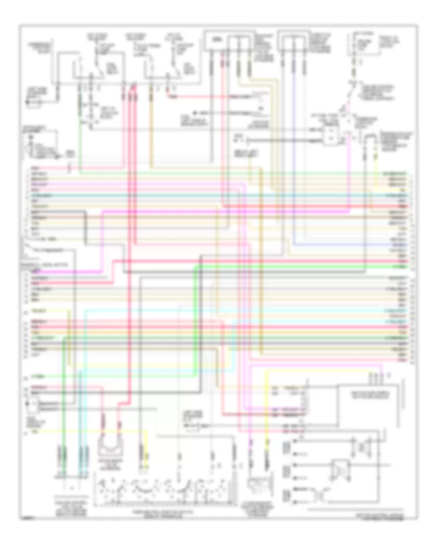
3.1L VIN J, Engine Performance Wiring Diagrams (1 of 3) for Chevrolet Malibu LS 1999
List of elements for 3.1L VIN J, Engine Performance Wiring Diagrams (1 of 3) for Chevrolet Malibu LS 1999:
- (left side of dash)
- 1-2 valve ctrl
- 2-3 valve ctrl
- 3x ref high
- 3x ref low
- 5v ref
- A/t iss sensor high
- A/t iss sensor low
- Air sol ctrl
- Automatic transaxle
- Automatic transaxle input shaft speed sensor
- Batt voltage
- Brake sw input
- Bypass control
- Ckp sensor
- Cmp sensor signal
- Cooling fans system
- Cruise control system
- Cruise disable
- Data link connector
- Egr sol valve
- Evap canp driver
- Evaporative emission canister purge valve (top right rear of engine)
- Evaporative emission canister vent solenoid (under rear of vehicle)
- Fan 2 ctrl
- Fuel inj 1
- Fuel inj 2
- Fuel inj 3
- Fuel inj 5
- Fuel injectors
- G125 (front of engine)
- Ho2s 1 low
- Ho2s 2 low
- Hot at all times
- Hot in accy, run or start
- Hot in run or start
- Iac coil b high
- Ic control
- Ign
- Ign mod fuse 10a
- Inj 6 driver
- Instrument cluster system (vehicle speed signal)
- Intake air temperature (iat) sensor (in air intake duct, near throttle body)
- Knock sensor (left side of engine)
- Ks signal
- Left i/p junction block
- Maf sensor
- Mass airflow sensor (on air intake duct assembly)
- Pcm acc fuse 10a
- Pcm batt fuse 10a
- Pcm ground
- Pnk
- Powertrain control module (below left side of dash)
- S101 (injector harness, 16 cm from in-line connec- tor)
- Sensor ground
- Serial data
- Tan
- Tr sw input b
- Trans range a
- Underhood junction block
- Vehicle speed sensor (rear of transaxle)
- Vss high
- Vss low
- Vss output
3.1L VIN J, Engine Performance Wiring Diagrams (2 of 3) for Chevrolet Malibu LS 1999
List of elements for 3.1L VIN J, Engine Performance Wiring Diagrams (2 of 3) for Chevrolet Malibu LS 1999:
- (below left front seat)
- (left side of engine) g112
- (top rear of engine)
- 7x crankshaft position sensor (lower right of engine)
- A4 (at fuel tank)
- Air pump (on engine)
- Air pump fuse 30a
- Air pump relay
- Air solenoid valve (on engine)
- Auto trans fuse 10a
- B11
- Cruise control brake switch (on brake pedal support)
- Cruise fuse 10a
- Engine coolant temperature sensor (top rear of engine)
- Engine oil level switch (in oil pan)
- Exhaust gas recirc- ulation valve
- F/p injr fuse 15a
- Fuel pump relay
- Fuel tank module
- G100 (left side of engine compt)
- G125 (front of engine)
- G300
- Hot at all times
- Hot in run
- Hot in run or start
- Idle air control (iac) valve (on top center rear of engine)
- Ign
- Ignition amplifier & switching module
- Ignition control module (top front of engine)
- Instrument cluster
- Left i/p junction block
- Mal- function indicator lamp
- Nca
- Park/neutral position switch (side of transaxle)
- Plugs spark
- Pnk
- Red
- Right i/p junction block
- Spark plugs
- Tan
- Throttle position sensor (top rear of engine)
- Underhood junction block
3.1L VIN J, Engine Performance Wiring Diagrams (3 of 3) for Chevrolet Malibu LS 1999
List of elements for 3.1L VIN J, Engine Performance Wiring Diagrams (3 of 3) for Chevrolet Malibu LS 1999:
- 2-3 shift sole- noid valve
- 24x crankshaft position sensor (lower front of engine)
- 5v ref
- A/c clutch rly ctrl
- A/c refrig pres sens
- A/c refrigerant pressure sensor (front of engine)
- A/c system
- Air pump relay ctrl
- Automatic transaxle
- Automatic transaxle fluid pressure valve manual pos switch
- Automatic transaxle fluid temp sensor
- C11
- Camshaft position sensor (front of engine)
- Cooling fans system
- Cruise control system
- Cruise engaged
- Ect densor
- Egr pos signal
- Egr valve ctrl
- Eng oil level input
- Engine oil pressure sensor (left side of engine)
- Erls fuse 10a
- Evap canv driver
- Fan 2 ctrl
- Fuel inj 4
- Fuel pump relay ctrl
- Fuel tank pressure
- Fuel tank pressure sensor (under rear of vehicle)
- G202 (left side of dash)
- Generator term f
- Generator term l
- Heated front oxygen sensor (right side exhaust manifold)
- Heated rear oxygen sensor (rear of catalytic converter)
- Ho2s 1 signal
- Ho2s 2 signal
- Hot in run
- Hot in run or start underhood junction block
- Iac coil a hi
- Iac coil a low
- Iac coil b
- Iat sensor
- Ign
- Ign voltage
- Instrument cluster (tachometer)
- Left i/p junction block
- Manifold absolute pressure sensor (attached to bracket on top of engine)
- Map signal
- Mil ctrl
- Nca
- Oil pres sensor
- Pc sol high
- Pc sol low
- Pcm ign fuse 10a
- Pnk
- Pnk e
- Pnk n
- Powertrain control module (below left side of dash)
- Pressure control solenoid valve
- Red
- Red p
- Red/
- Sensor gnd
- Start- ing/ charging system
- Starting/ charging system
- Tach out
- Tan
- Tcc pwm sol
- Tcc pwm sole- noid valve
- Tcc rel sw
- Tft sensor
- Tp sensor
- Tr sw b
- Tr switch a
- Tr switch c
- Tr switch d
3.1L VIN M, Engine Performance Wiring Diagrams (1 of 3) for Chevrolet Malibu LS 1999
List of elements for 3.1L VIN M, Engine Performance Wiring Diagrams (1 of 3) for Chevrolet Malibu LS 1999:
- (left side of dash)
- 1-2 valve ctrl
- 2-3 valve ctrl
- 3x ref high
- 3x ref low
- 5v ref
- A/t iss sensor high
- A/t iss sensor low
- Automatic transaxle
- Automatic transaxle input shaft speed sensor
- Batt voltage
- Brake sw input
- Bypass control
- Ckp sensor
- Cmp sensor signal
- Cooling fans system
- Cruise control system
- Cruise disable
- Data link connector
- Egr sol valve
- Evap canp driver
- Evaporative emission canister purge valve (top right rear of engine)
- Evaporative emission canister vent solenoid (under rear of vehicle)
- Fan 1 ctrl
- Fan 2 ctrl
- Fuel inj 1
- Fuel inj 2
- Fuel inj 3
- Fuel inj 5
- Fuel injectors
- G125 (front of engine)
- Ho2s 1 low
- Ho2s 2 low
- Hot at all times
- Hot in accy, run or start
- Hot in run or start
- Iac coil b high
- Ic control
- Ign
- Ign mod fuse 10a
- Inj 6 driver
- Instrument cluster system (vehicle speed signal)
- Intake air temperature (iat) sensor (in air intake duct, near throttle body)
- Knock sensor (left side of engine)
- Ks signal
- Left i/p junction block
- Maf sensor
- Mass air flow sensor (on air intake duct assembly)
- Pcm acc fuse 10a
- Pcm batt fuse 10a
- Pcm ground
- Pnk
- Powertrain control module (below left side of dash)
- S101 (injector harness, 16 cm from in-line connec- tor)
- Sensor ground
- Serial data
- Tan
- Tr sw input b
- Trans range a
- Underhood junction block
- Vehicle speed sensor (rear of transaxle)
- Vss high
- Vss low
- Vss output
3.1L VIN M, Engine Performance Wiring Diagrams (2 of 3) for Chevrolet Malibu LS 1999
List of elements for 3.1L VIN M, Engine Performance Wiring Diagrams (2 of 3) for Chevrolet Malibu LS 1999:
- (left side of engine) g112
- (top front of engine) ignition control module
- (top rear of engine)
- 7x crankshaft position sensor (lower right of engine)
- B11
- Cruise control brake switch (on brake pedal support)
- Cruise fuse 10a
- Engine coolant temperature sensor (top rear of engine)
- Engine oil level switch (in oil pan)
- Exhaust gas recirc- ulation valve
- F/p injr fuse 15a
- Fuel pump relay
- Fuel tank module (at fuel tank)
- G125 (front of engine)
- G300 (below left front seat)
- Hot in run
- Hot in run or start
- Idle air control (iac) valve (on top center rear of engine)
- Ign
- Ignition amplifier and switching module
- Instrument cluster
- Left i/p junction block
- Mal- function indicator lamp
- Nca
- Park/neutral position switch (side of transaxle)
- Plugs spark
- Pnk
- Red
- Right i/p junction block
- Spark plugs
- Tan
- Throttle position sensor (top rear of engine)
- Underhood junction block
3.1L VIN M, Engine Performance Wiring Diagrams (3 of 3) for Chevrolet Malibu LS 1999
List of elements for 3.1L VIN M, Engine Performance Wiring Diagrams (3 of 3) for Chevrolet Malibu LS 1999:
- 2-3 shift sole- noid valve
- 24x crankshaft position sensor (lower front of engine)
- 5v ref
- A/c clutch relay ctrl
- A/c refrig pres sensor
- A/c refrigerant pressure sensor (front of engine)
- A/c system
- Auto trans fuse 10a
- Automatic transaxle
- Automatic transaxle fluid pressure valve manual pos switch
- Automatic transaxle fluid temp sensor
- C11
- Camshaft position sensor (front of engine)
- Cruise control system
- Cruise engaged
- Ect densor
- Egr pos signal
- Egr valve ctrl
- Eng oil level input
- Engine oil pressure sensor (left side of engine)
- Erls fuse 10a
- Evap canv driver
- Fuel inj 4
- Fuel pump relay ctrl
- Fuel tank pressure
- Fuel tank pressure sensor (under rear of vehicle)
- G202 (left side of dash)
- Generator term f
- Generator term l
- Ho2s 1 signal
- Ho2s 2 signal
- Hot in run
- Hot in run or start
- Iac coil a hi
- Iac coil a low
- Iac coil b
- Iat sensor
- Ign
- Ign voltage
- Instrument cluster (tachometer)
- Left i/p junction block
- Manifold absolute pressure sensor (attached to bracket on top of engine)
- Map signal
- Mil ctrl
- Nca
- Oil pres sensor
- Pc sol high
- Pc sol low
- Pcm/ign fuse 10a
- Pnk
- Pnk e
- Pnk n
- Post converter heated oxygen sensor (rear of catalytic converter)
- Powertrain control module (below left side of dash)
- Pre-converter heated oxygen sensor (right side exhaust manifold)
- Pressure control solenoid valve
- Red
- Red p
- Red/
- Sensor gnd
- Start- ing/ charging system
- Starting/ charging system
- Tach out
- Tan
- Tcc pwm sol
- Tcc pwm sole- noid valve
- Tcc rel sw
- Tft sensor
- Tp sensor
- Tr sw b
- Tr switch a
- Tr switch c
- Tr switch d
- Underhood junction block