ENGINE PERFORMANCE
5.7L
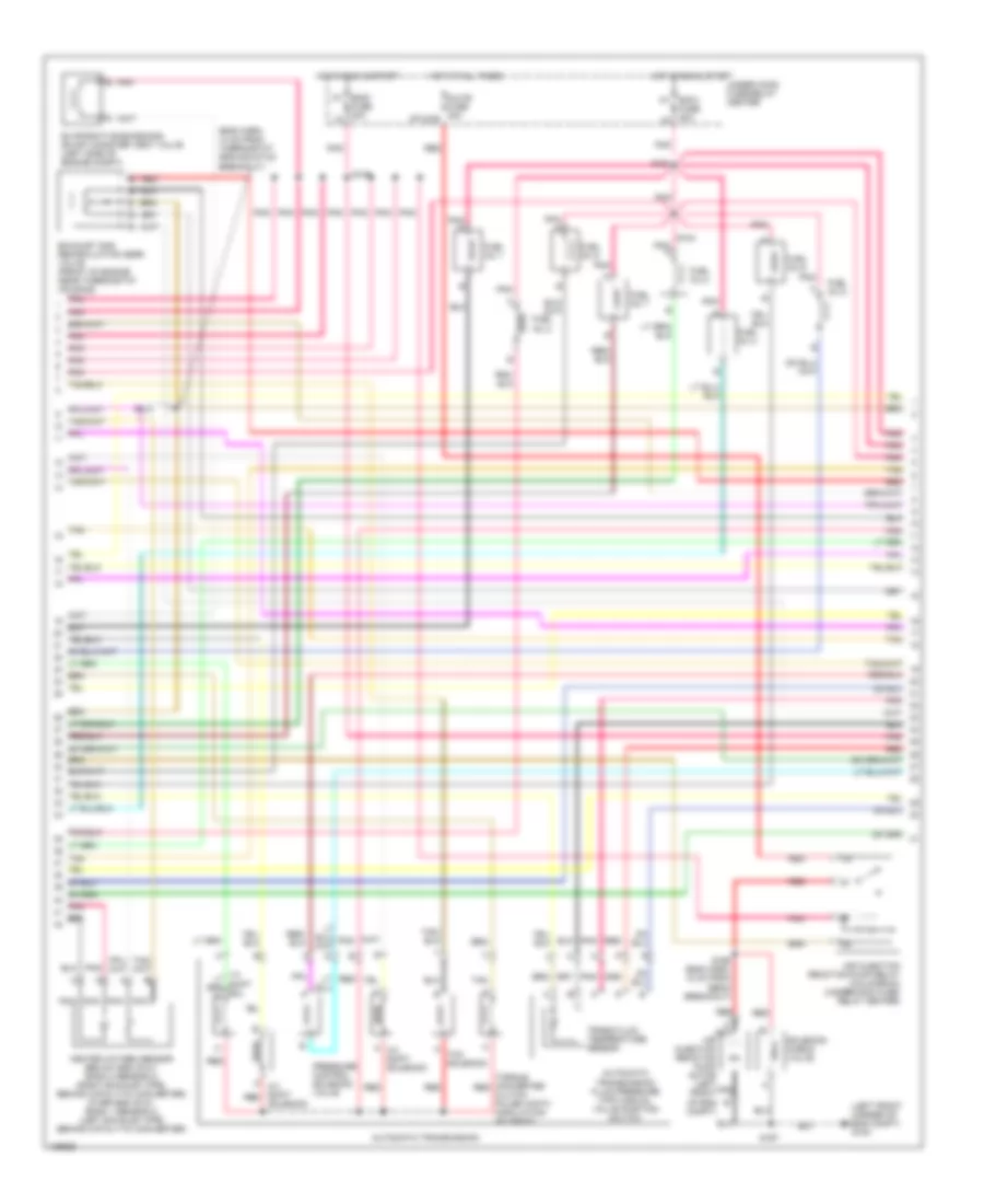
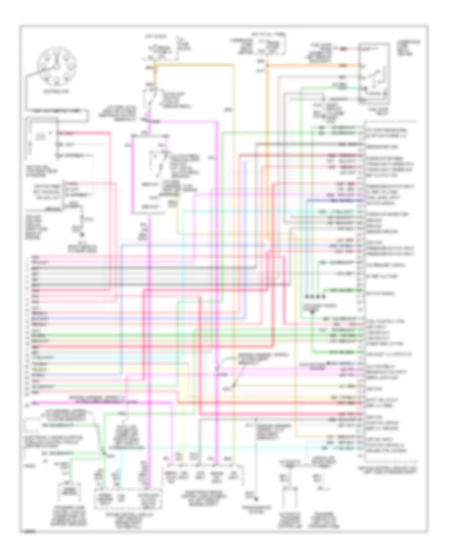
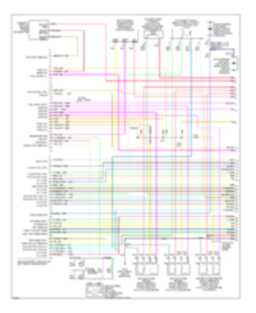
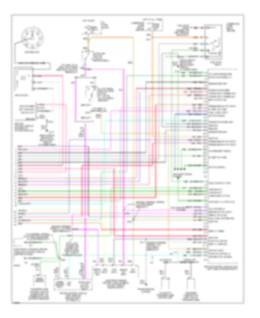
5.7L VIN K, Engine Performance Wiring Diagrams (1 of 6) for Chevrolet Pickup C3500 2000

List of elements for 5.7L VIN K, Engine Performance Wiring Diagrams (1 of 6) for Chevrolet Pickup C3500 2000:
- (attached to right rear of throttle body) idle air control (iac) valve
- (bottom front of engine near, crank pulley) crankshaft position sensor
- (eng harn, 13 cm from fuse/relay center)
- (eng harn, 13 cm from starter solenoid breakout)
- (eng harn, 20 cm from fuse/relay center)
- (eng harn, 6.5 cm from cps breakout)
- (eng harn, 6.5 cm from starter solenoid breakout)
- (engine harn, 17 cm from under- hood fuse/relay center nreakout)
- (top right side of engine) evaporative emission canister purge solenoid valve
- 1-2 shift sol ctrl
- 2-3 shift sol ctrl
- 3-2 shift sol ctrl
- A/t w/ 4wd
- Air pump rel ctrl
- Cam posit sens sig
- Camshaft position sensor (inside distributor)
- Crank posit sens sig
- Ect sens sig
- Egr posit sig
- Fuel gauge lvl
- Fuel tank press sens
- G119 (right front of engine block)
- Heated oxygen sensor (bank 1 sensor 1) (in left exhaust pipe, in front of catalytic converter)
- Heated oxygen sensor (bank 2 sensor 1) (in right exhaust pipe, in front of catalytic converter)
- Heated oxygen sensor (below 8600 gvw: bank 1 sensor 2) (left exhaust pipe, behind catalytic converter (over 8600 gvw: bank 2 sensor 2) (right exhaust pipe, behind catalytic converter)
- Ho2s low
- Ho2s sig
- Iat sens sig
- Idle air ctrl (iac) a hi
- Idle air ctrl (iac) b lo
- Ign feed
- Inj 1 ctrl
- Inj 2 ctrl
- Inj 3 ctrl
- Inj 4 ctrl
- Inj 5 ctrl
- Inj 6 ctrl
- Inj 7 ctrl
- Inj 8 ctrl
- Inline gender adapter a
- Knock sens sig
- Knock sensor (ks) (right side of engine block, below exhaust manifold, forward of starter)
- Low ref
- Map sens input
- Mass air flow sens sig
- Nca
- Others
- Pnk
- Pnk c ignition feed
- S012
- S013
- S016
- S021
- S022
- S031
- S148
- S149
- S162
- Sens rtn
- Sens sig
- Sensor return
- Tan
- Tcc pwm sol ctrl
- Tcc sol ctrl
- Temp sens input
- Throttle posit sens
- Vehicle control module (vcm) (left side of engine compt)
- Vehicle speed sensor (left side of transmission, left side of transfer case w/ 4wd)
- Vent ctlr
- Vss sig
- Vss signal
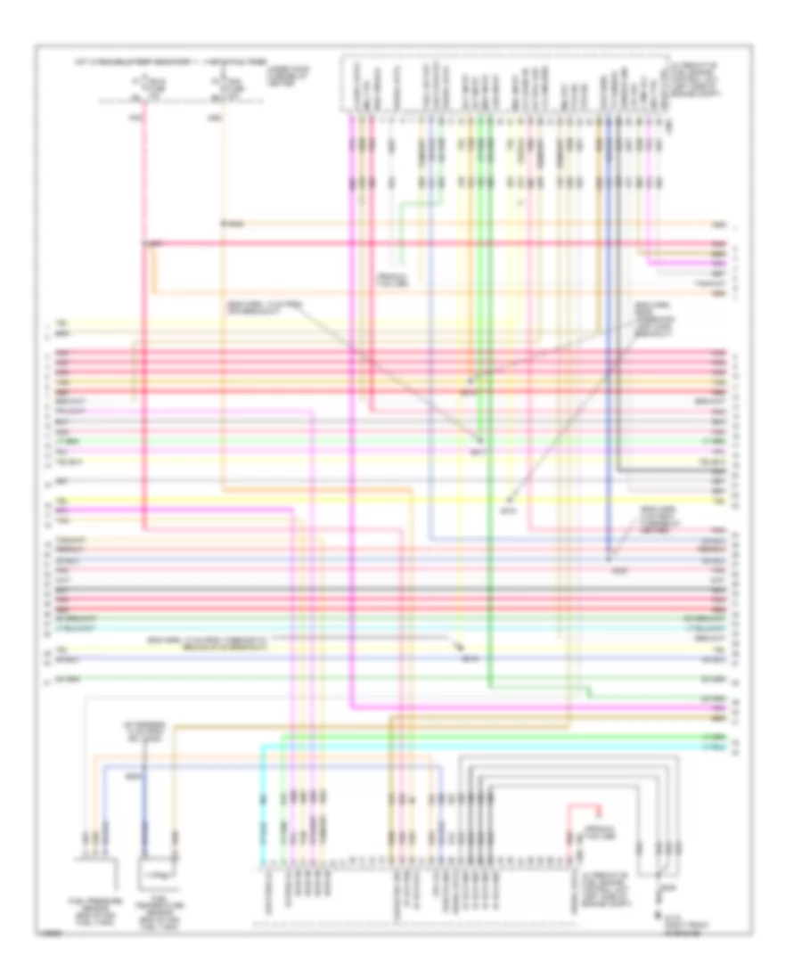
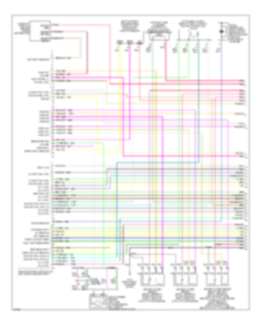
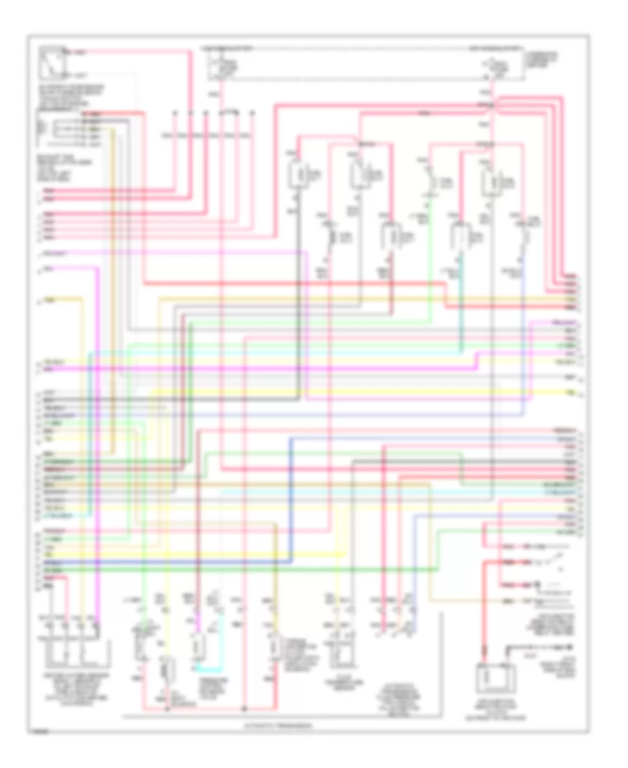
5.7L VIN K, Engine Performance Wiring Diagrams (2 of 6) for Chevrolet Pickup C3500 2000
List of elements for 5.7L VIN K, Engine Performance Wiring Diagrams (2 of 6) for Chevrolet Pickup C3500 2000:
- (eng harn, 14 cm from thermostat ground stud breakout)
- (left front corner of eng compt) g100
- A 2-3 shift red
- A 3-2 shift solenoid
- A nca
- Air injection reaction pump motor (left front of eng compt)
- Air injection reaction pump relay (california) (underhood fuse/ relay center)
- Automatic transmission
- Automatic transmission fluid pressure (tfp) manual valve position switch
- Aux-b fuse 30a stud-b
- Ecm1 fuse 20a
- Eng1 k7
- Evaporative emissions (evap) canister vent valve (left side of engine compt)
- Exhaust gas recirculation (egr) valve (front of engine near thermostat housing)
- Fuel inj 1
- Fuel inj 2
- Fuel inj 3
- Fuel inj 4
- Fuel inj 5
- Fuel inj 6
- Fuel inj 7
- Fuel inj 8
- Fuse 20a l8
- Heated oxygen sensor (below 8600 gvw: bank 2 sensor 2) (right exhaust pipe, behind catalytic converter) (over 8600 gvw: bank 1 sensor 2) (left exhaust pipe behind catalytic converter)
- Hot at all times
- Hot in run & start
- Nca
- Pnk
- Pnk a
- Pressure control solenoid valve
- Red
- S018
- S104 pnk a
- S108
- S161
- S166 (eng harn, 18 cm from ebcm breakout)
- S167
- Solenoid
- Solenoid check valve
- Tan
- Tcc solenoid
- Torque converter red clutch pulse width modulation solenoid
- Trans fluid temperature sensor
- Under hood fuse/relay center
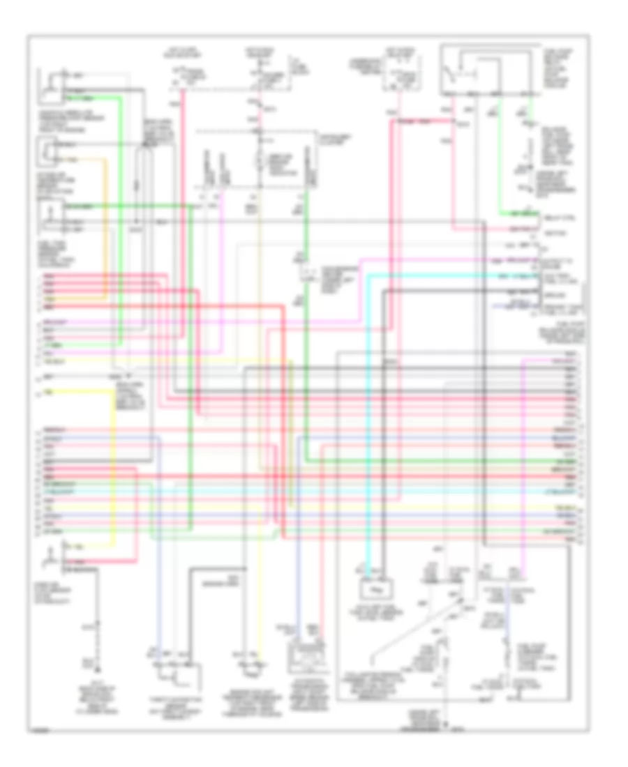
5.7L VIN K, Engine Performance Wiring Diagrams (3 of 6) for Chevrolet Pickup C3500 2000
List of elements for 5.7L VIN K, Engine Performance Wiring Diagrams (3 of 6) for Chevrolet Pickup C3500 2000:
- (af harness, 10 cm from hpl conn)
- (eng harn, 10 cm from thermostat ground stud breakout)
- (eng harn, 13 cm from cps breakout)
- (eng harn, 4 cm from fuse/relay center)
- (eng harn, near underhood lamp conn breakout)
- (produc- tion use)
- +5v ref
- 1x cam sens
- 4x crank in
- Actual gas
- Af ecu bat
- Af ecu gnd
- Af ecu ign
- Alternative fuel engine control unit (left side of engine compt)
- C001
- C002
- Class 2 data
- Cng fuse 20a
- Ect input
- Egr sens
- F pmp rly
- Fps +5v
- Fps sig
- Fps/fts gnd
- Fts sig
- Fuel lev out
- Fuel pressure sensor (end of cng fuel tank)
- Fuel temperature sensor (end of cng fuel tank)
- G119 (right front of engine)
- Gas flow out
- Gauge sel sw
- Hi pres lo
- Ho2s in
- Hot at all times
- Hot in run, bulb test and start
- Iat input
- Ign e fuse 10a
- Ind ctrl
- Low pres lo
- Maf input
- Map input
- Mil ctrl
- Mil out
- Ngo enable
- Pnk
- Red
- Relay ctrl
- S001
- S002
- S009
- S014
- S015
- S017
- S019
- S020
- S399
- Sensor gnd
- Serial data
- Tan
- Tp sensor
- Under hood fuse/relay center
- Vss input
5.7L VIN K, Engine Performance Wiring Diagrams (4 of 6) for Chevrolet Pickup C3500 2000
List of elements for 5.7L VIN K, Engine Performance Wiring Diagrams (4 of 6) for Chevrolet Pickup C3500 2000:
- (af harn, 32.5 cm from relay breakout)
- (af harn, near lpl breakout)
- Af d1 (af harn 10 cm from hpl conn)
- Af d2 (af harn 10 cm from lpl conn)
- Af fuel pump relay (left of engine compt)
- Fuel gauge relay (left of engine compt)
- Fuel gauge select switch
- G119 (right front of engine)
- Gas mass sensor (right front of engine)
- High pressure lock-off solenoid (end of cng fuel tank)
- Ignition relay (left of engine compt)
- Interior lights system
- Lock-off relay (left of engine compt)
- Low pressure lock-off solenoid (right middle of engine)
- Mixture control valve motor (right front of engine)
- Nca
- Pnk
- Red
- S003 (af harn, 22.5 cm from relay breakout)
- S004
- S005 (af harn, 13 cm from conn breakout)
- S009
- S010
- S011
- S398 (af harn, near breakout to hpl conn)
- S399
- Tan
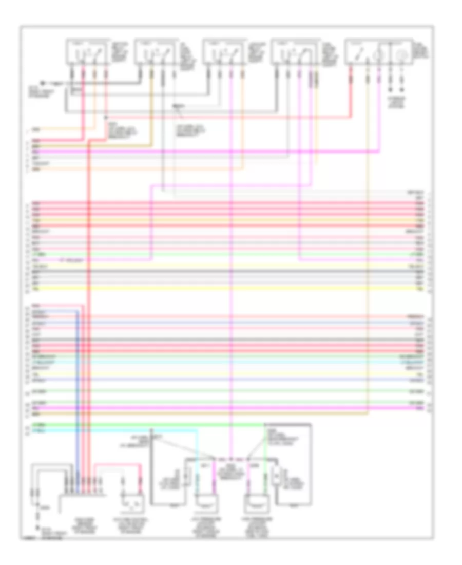
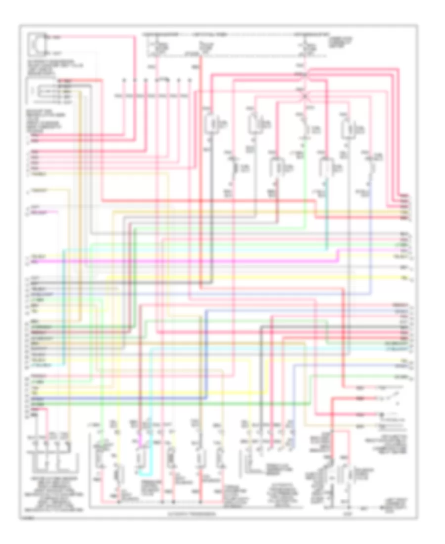
5.7L VIN K, Engine Performance Wiring Diagrams (5 of 6) for Chevrolet Pickup C3500 2000
List of elements for 5.7L VIN K, Engine Performance Wiring Diagrams (5 of 6) for Chevrolet Pickup C3500 2000:
- (eng harn, approx 17 cm from breakout to egr valve) s106
- (eng harn, hd: 10 cm from egr valve breakout, ld: 27 cm from egr valve breakout)
- (engine harn, approx 16 cm from breakout to egr valve)
- (inside left frame rail, near rear crossmember)
- (right rear of cylinder head) g117
- (taillamp extension harn, 6 cm from the fuel pump harn breakout)
- Automatic transmission input shaft speed sensor (left side of transmission)
- C100
- C223
- Convenience center (under left side of dash)
- Engine coolant temperature sensor (top right front of engine, near thermostat housing)
- Fuel gauge input
- Fuel pump & sender (in fuel tank)
- Fuel tank pressure sensor (in fuel tank)
- G415
- Gauges fuse 4 10a
- Grd
- Hot in off, run or start
- Hot in run or start
- I/p fuse block
- Ign
- Instrument cluster
- Intake air temperature sensor (in air intake duct)
- M/t only
- Manifold absolute pressure (map) sensor (top right of engine, near fuel injectors)
- Mass airflow sensor (in air intake duct)
- Pnk
- Red
- S103
- S131
- S213
- S231
- S232
- S430
- Service engine soon indicator
- Sig
- Speedometer input
- Tachometer input
- Tan
- Tan a
- Throttle position sensor (on throttle body assembly)
- Trans fuse 20 10a
- Upshift lamp
- W/o dual fuel tank
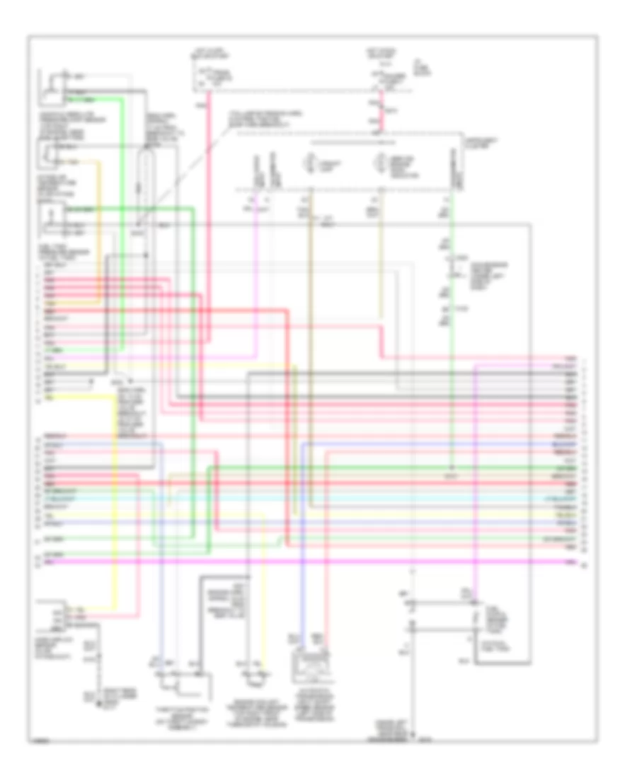
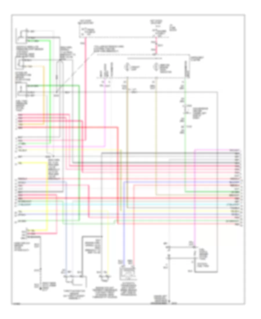
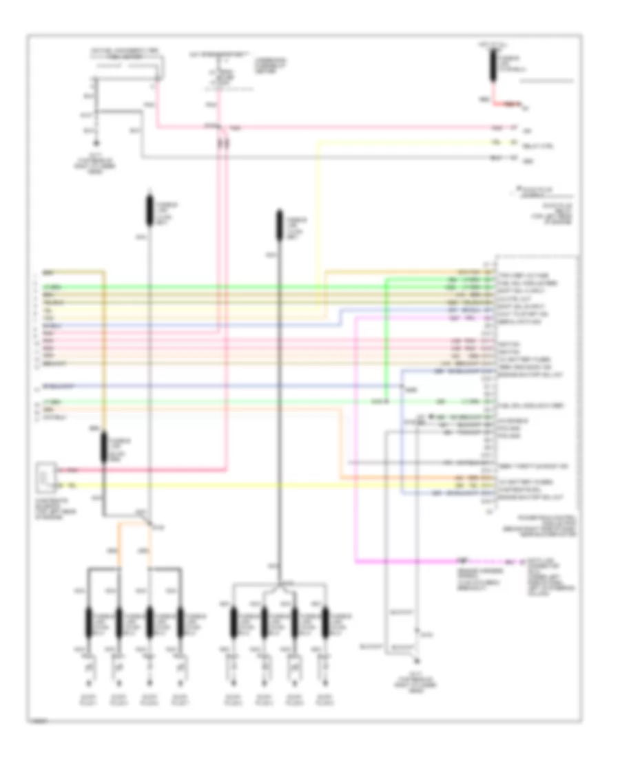
5.7L VIN K, Engine Performance Wiring Diagrams (6 of 6) for Chevrolet Pickup C3500 2000
List of elements for 5.7L VIN K, Engine Performance Wiring Diagrams (6 of 6) for Chevrolet Pickup C3500 2000:
- (engine harness, approx 13 cm from ebcm breakout) s150
- (engine harness, approx 7 cm from ebcm breakout)
- (i/p harn, 20 cm from inflatable restraint switch breakout)
- (i/p harn, harness, 13 cm from left engine grommet)
- (i/p harness, approx 40 cm from instrument cluster breakout)
- (or
- (right rear of cylinder head) g120
- 4wd input
- 5v ref voltage
- 87a
- A pnk
- A/c comp enable rel
- A/c request signal
- A/t
- Air conditioning system
- Air inlet vlv mtr ctlr
- Automatic 4wd
- Automatic transfer case shift controller
- Aux fan relay
- Brake sw input
- Brake switch input
- Check eng lp ctrl
- Clutch pedal position (cpp) switch (at top of clutch pedal bracket)
- Cooling fans system
- Cpp sw input
- Cruise control module (left rear of engine compt, on firewall)
- Cruise ctrl sig eng
- Data link connector (under left side of dash, left side of steering column)
- Distributor
- Egr vlv feed
- Egr vlv ground
- Electronic brake control module (ebcm) (on left side of engine compt)
- Electronic variable orifice/ passlock control module (center of dash)
- Est output sig
- Evap can purge vlv
- F11 ecmb fuse 20a
- Force motor feed
- Force motor return
- Four whl dr sig
- Four whl dr sig lo
- Fuel level input
- Fuel pump a prime connector (left rear of eng compt)
- Fuel pump relay
- Fuel pump rly ctrl
- G117 (right rear of cylinder head)
- G12
- Ground
- High voltage coil wire
- Hot at all times
- Hot in run
- I/p fuse block
- Ign coil out
- Ign input
- Ign timing sig.
- Ignition
- Ignition coil (top right rear of engine)
- Ignition control module (right side rear of engine)
- Ignition feed
- M/t
- M4 brake fuse 18 10a n3
- Manual or selectable 4wd
- Ngo input
- Pnk
- Pressure switch input
- Radio
- Red
- S101
- S103
- S111 (engine harness, approx 10 cm from ebcm breakout)
- S151
- S152
- S153
- S221
- Sensor ground
- Sensor return
- Serial data sig
- Shift ind lp out
- Speed sensor
- Speed sensor input
- Stoplamp switch (top of brake pedal)
- Stoplamp/ clutch switch input
- Switch signal
- Trans input speed rtn
- Trans input speed sig
- Transfer case control module (under dash, on steering column support bracket)
- Transfer case switch (left top of transfer case)
- Transmissions system
- Underhood fuse/ relay center
- Vcm sig
- Vehicle control module (vcm) (left side of engine compt)
- Vss input
- Vss sig out
5.7L VIN R, Engine Performance Wiring Diagrams (1 of 4) for Chevrolet Pickup C3500 2000
List of elements for 5.7L VIN R, Engine Performance Wiring Diagrams (1 of 4) for Chevrolet Pickup C3500 2000:
- (attached to right rear of throttle body) idle air control (iac) valve
- (bottom front of engine near, crank pulley) crankshaft position sensor
- (top right side of engine) evaporative emission canister purge solenoid valve
- 1-2 shift sol ctrl
- 2-3 shift sol ctrl
- 3-2 shift sol ctrl
- A/t w/ 4wd
- Air pump rel ctrl
- Cam posit sens sig
- Camshaft position sensor (inside distributor)
- Crank posit sens sig
- Ect sens sig
- Egr posit sig
- Fuel gauge lvl
- Fuel tank press sens
- G119 (right front of engine block)
- Heated oxygen sensor (bank 1 sensor 1) (in left exhaust pipe, in front of catalytic converter)
- Heated oxygen sensor (bank 2 sensor 1) (in right exhaust pipe, in front of catalytic converter)
- Heated oxygen sensor (below 8600 gvw: bank 1 sensor 2) (left exhaust pipe, behind catalytic converter (over 8600 gvw: bank 2 sensor 2) (right exhaust pipe, behind catalytic converter)
- Ho2s low
- Ho2s sig
- Iat sens sig
- Idle air ctrl (iac) a hi
- Idle air ctrl (iac) b lo
- Ign feed
- Inj 1 ctrl
- Inj 2 ctrl
- Inj 3 ctrl
- Inj 4 ctrl
- Inj 5 ctrl
- Inj 6 ctrl
- Inj 7 ctrl
- Inj 8 ctrl
- Inline gender adapter a
- Knock sens sig
- Knock sensor (ks) (right side of engine block, below exhaust manifold, forward of starter)
- Low ref
- Map sens input
- Mass air flow sens sig
- Nca
- Others
- Pnk
- Pnk c ignition feed
- Pnk pnk
- S148
- S149
- S162
- Sens rtn
- Sens sig
- Sensor return
- Tan
- Tcc pwm sol ctrl
- Tcc sol ctrl
- Temp sens input
- Throttle posit sens
- Vehicle control module (vcm) (left side of engine compt)
- Vehicle speed sensor (left side of transmission, left side of transfer case w/ 4wd)
- Vent ctlr
- Vss sig
- Vss signal
5.7L VIN R, Engine Performance Wiring Diagrams (2 of 4) for Chevrolet Pickup C3500 2000
List of elements for 5.7L VIN R, Engine Performance Wiring Diagrams (2 of 4) for Chevrolet Pickup C3500 2000:
- (left front corner of eng compt) g100
- A 2-3 shift red
- A 3-2 shift solenoid
- A nca
- Air injection reaction pump motor (left front of eng compt)
- Air injection reaction pump relay (california) (underhood fuse/ relay center)
- Automatic transmission
- Automatic transmission fluid pressure (tfp) manual valve position switch
- Aux-b fuse 30a stud-b
- Ecm1 fuse 20a
- Eng1 k7
- Evaporative emissions (evap) canister vent valve (left side of engine compt)
- Exhaust gas recirculation (egr) valve (front of engine near thermostat housing)
- Fuel inj 1
- Fuel inj 2
- Fuel inj 3
- Fuel inj 4
- Fuel inj 5
- Fuel inj 6
- Fuel inj 7
- Fuel inj 8
- Fuse 20a l8
- Heated oxygen sensor (below 8600 gvw: bank 2 sensor 2) (right exhaust pipe, behind catalytic converter) (over 8600 gvw: bank 1 sensor 2) (left exhaust pipe behind catalytic converter)
- Hot at all times
- Hot in run & start
- Nca
- Pnk
- Pnk pnk pnk tan red
- Pressure control solenoid valve
- Red
- S104
- S108
- S161
- S166 (eng harn, 18 cm from ebcm breakout)
- S167
- Solenoid
- Solenoid check valve
- Tan
- Tcc solenoid
- Torque converter red clutch pulse width modulation solenoid
- Trans fluid temperature sensor
- Under hood fuse/relay center
5.7L VIN R, Engine Performance Wiring Diagrams (3 of 4) for Chevrolet Pickup C3500 2000
List of elements for 5.7L VIN R, Engine Performance Wiring Diagrams (3 of 4) for Chevrolet Pickup C3500 2000:
- (eng harn, approx 17 cm from breakout to egr valve) s106
- (eng harn, hd: 10 cm from egr valve breakout, ld: 27 cm from egr valve breakout)
- (engine harn, approx 16 cm from breakout to egr valve)
- (inside left frame rail, near rear crossmember)
- (right rear of cylinder head) g117
- (taillamp extension harn, 6 cm from the fuel pump harn breakout)
- Automatic transmission input shaft speed sensor (left side of transmission)
- C100
- C223
- Convenience center (under left side of dash)
- Engine coolant temperature sensor (top right front of engine, near thermostat housing)
- Fuel gauge input
- Fuel pump & sender (in fuel tank)
- Fuel tank pressure sensor (in fuel tank)
- G415
- Gauges fuse 4 10a
- Grd
- Hot in off, run or start
- Hot in run or start
- I/p fuse block
- Ign
- Input
- Instrument cluster
- Intake air temperature sensor (in air intake duct)
- M/t only
- Manifold absolute pressure (map) sensor (top right of engine, near fuel injectors)
- Mass airflow sensor (in air intake duct)
- Pnk
- Pnk pnk tan red
- S103
- S213
- S231
- S232
- S430
- Service engine soon indicator
- Sig
- Speedometer input
- Tachometer
- Tan a
- Throttle position sensor (on throttle body assembly)
- Trans fuse 20 10a
- Upshift lamp
- W/o dual fuel tank
5.7L VIN R, Engine Performance Wiring Diagrams (4 of 4) for Chevrolet Pickup C3500 2000
List of elements for 5.7L VIN R, Engine Performance Wiring Diagrams (4 of 4) for Chevrolet Pickup C3500 2000:
- (engine harness, approx 13 cm from s150
- (engine harness, approx 7 cm from ebcm breakout)
- (i/p harn, 20 cm from inflatable restraint switch breakout)
- (i/p harn, harness, 13 cm from left engine grommet)
- (i/p harness, approx 40 cm from instrument cluster breakout)
- (or
- (right rear of cylinder head) g120
- 4wd input
- 5v ref voltage
- 87a
- A pnk
- A/c comp enable rel
- A/c request signal
- A/t
- Air conditioning system
- Air inlet vlv mtr ctlr
- Automatic 4wd
- Automatic transfer case shift controller
- Aux fan relay
- Brake sw input
- Brake switch input
- Check eng lp ctrl
- Clutch pedal position (cpp) switch (at top of clutch pedal bracket)
- Cooling fans system
- Cpp sw input
- Cruise control module (left rear of engine compt, on firewall)
- Cruise ctrl sig eng
- Data link connector (under left side of dash, left side of steering column)
- Distributor
- Ebcm breakout)
- Egr vlv feed
- Egr vlv ground
- Electronic brake control module (ebcm) (on left side of engine compt)
- Electronic variable orifice/ passlock control module (center of dash)
- Est output sig
- Evap can purge vlv
- F11 ecmb fuse 20a
- Force motor feed
- Force motor return
- Four whl dr sig
- Four whl dr sig lo
- Fuel level input
- Fuel pump a prime connector (left rear of eng compt)
- Fuel pump relay
- Fuel pump rly ctrl
- G117 (right rear of cylinder head)
- G12
- Ground
- High voltage coil wire
- Hot at all times
- Hot in run
- I/p fuse block
- Ign coil out
- Ign input
- Ign timing sig.
- Ignition
- Ignition coil (top right rear of engine)
- Ignition control module (right side rear of engine)
- Ignition feed
- M/t
- M4 brake fuse 18 10a n3
- Manual or selectable 4wd
- Pnk
- Pressure switch input
- Radio
- Red
- S101
- S103
- S111 (engine harness, approx 10 cm from ebcm breakout)
- S151
- S152
- S153
- S221
- Sensor ground
- Sensor return
- Serial data sig
- Shift ind lp out
- Speed sensor
- Speed sensor input
- Stoplamp switch (top of brake pedal)
- Stoplamp/ clutch switch input
- Switch signal
- Trans input speed rtn
- Trans input speed sig
- Transfer case control module (under dash, on steering column support bracket)
- Transfer case switch (left top of transfer case)
- Transmissions system
- Underhood fuse/ relay center
- Vcm sig
- Vehicle control module (vcm) (left side of engine compt)
- Vss input
- Vss sig out
6.5L
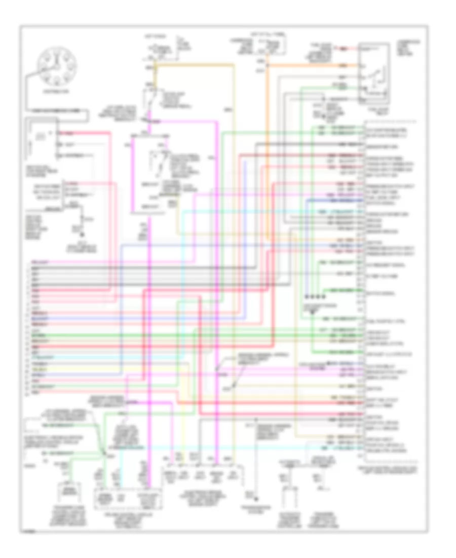
6.5L VIN F, Engine Performance Wiring Diagrams (1 of 4) for Chevrolet Pickup C3500 2000
List of elements for 6.5L VIN F, Engine Performance Wiring Diagrams (1 of 4) for Chevrolet Pickup C3500 2000:
- (bottom front of engine, near crank pulley) crankshaft position (ckp) sensor
- (engine harn, 31 cm from taillamp harn breakout)
- (i/p harn, approx 16 cm into i/p cluster breakout)
- (top center of engine) boost pressure sensor
- (top of engine, near
- (top rear of right cylinder head) g117
- (top right front of engine, near thermostat housing) engine coolant temperature (ect) sensor
- 4wd signal
- 5 volt ref
- 5 vref
- 5v ref volt
- A 1-2 red shift sol
- A 2-3 red shift sol
- A torque red converter clutch pulse wdth mod sol
- A/c request sig
- A/c system
- A/t fluid pressure (tfp) manual valve position switch
- A/t w/ 4wd
- A10
- A11 3 mode cruise a12
- Anti-lock brakes system
- App 1 sig
- App 2 sig
- App 3 sig
- Automatic transmission
- Automatic transmission input shaft speed (a/t iss) sensor (left side of transmission)
- B10
- B11
- B12
- Brake sw in
- Brake switch input
- C10
- C11
- C12
- C13
- C14
- C15
- C16
- Cam posit sens sig rtn
- Camshaft posit sens
- Closure gnd
- Cruise control system
- Cruise ctrl sw engage
- Cruise eng sw retard
- D10
- D11
- D12
- D13
- D14
- D15
- D16
- Ect temp sens in
- Engine crank sens input
- Force mtr hi
- Force mtr low
- Fuel pump input
- Fuel pump rly ctrl
- Fuel sol closure (5v sig)
- Fuel temp sens (5v sig)
- Glow plug "wait" lp out
- Glow plug relay
- Ground
- Ign
- Inline gender adapter
- Intake air temperature (iat) sensor
- Intake man air temp sens
- Intake manifold
- Map sens input
- Nca
- Opening)
- Others
- Pnk
- Powertrain control module (pcm) (behind right side of dash, near blower motor)
- Pressure control solenoid valve
- Radio, evo/ passlock control module, transfer case control module
- Range mode sel a
- Range mode sel b
- Range mode sel c
- Red
- S140
- S170
- S199
- S211
- S215
- Sensor gnd
- Tan
- Timing stepper mtr (high)
- Timing stepper mtr (low)
- Transmission speed input
- Transmission temp input
- Transmission temperature sensor
- Transmissions system
- Vehicle speed input
- Vehicle speed sensor (left side of transmission)
- Vehicle speed sensor buffer (behind right side of dash)
- Vss hi
- Vss lo
- Vss output
- Vss rtn
- Vss sig
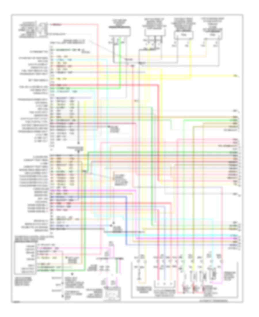
6.5L VIN F, Engine Performance Wiring Diagrams (2 of 4) for Chevrolet Pickup C3500 2000
List of elements for 6.5L VIN F, Engine Performance Wiring Diagrams (2 of 4) for Chevrolet Pickup C3500 2000:
- (a/t: eng harn, approx 4 cm from i/p harness breakout, m/t: i/p harn, 20 cm from inflatable restraint i/p module switch breakout)
- (on inj pump)
- 5 volt ref
- Accelerator pedal position (app) module (part of accelerator pedal)
- Clutch pedal position (cpp) switch (m/t only) (top of clutch pedal bracket)
- Cmp sig
- D2 trans fuse 20 20a e1
- D8 stop/haz fuse 1 20a c7
- Ecm-1 h7
- Electronic brake control module (on left side of engine compt)
- Engine shutoff solenoid (top of fuel injection pump)
- Fuel solenoid (rear of fuel injection pump)
- Fuel solenoid driver (left side of fuel injection pump)
- Fuse 20a
- High res sig
- Hot at all times
- Hot in run
- Hot in run or start
- I/p fuse block
- Injection timing stepper motor (top right front of engine)
- M4 brake fuse 18 10a n3
- Nca
- Optical fuel temperature sensor (on top of fuel injection pump)
- Pnk
- Pnk pnk
- Power distribution system
- Red
- S166
- S190
- S198
- S220 (i/p harness, approx 6 cm from steering column breakout)
- S222 (m/t) s152 (a/t)
- S299
- Sens grd
- Stop- lamp switch (on top of brake pedal)
- Tan d
- Underhood fuse/relay center
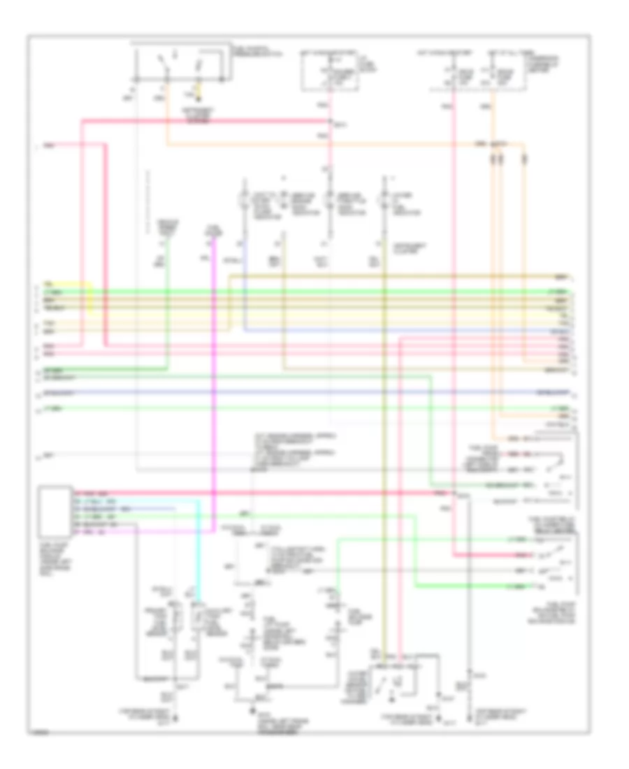
6.5L VIN F, Engine Performance Wiring Diagrams (3 of 4) for Chevrolet Pickup C3500 2000
List of elements for 6.5L VIN F, Engine Performance Wiring Diagrams (3 of 4) for Chevrolet Pickup C3500 2000:
- (inside left frame rail, below driver's door)
- (m/t: engine harness, approx 37 cm from breakout to ebcm, a/t: engine harness, approx 31 cm from taillamp harn breakout) s100
- (taillamp ext harn, 10 cm from fuel pump balance mod breakout)
- (top rear of right cylinder head)
- (top rear of right cylinder head) g117
- Auxiliary tank fuel level sensor
- Ecm-b fuse 20a
- F11
- Fuel balance pump
- Fuel gauge
- Fuel lift pump
- Fuel pump balance module (inside left side frame rail)
- Fuel pump balance relay (on fuel pump balance module)
- Fuel pump prime connector (left side of eng compt)
- Fuel pump relay (in under fuse- relay center)
- Fuel pump/oil pressure switch
- G117
- G12
- G415 (inside left frame rail, near rear crossmember)
- Gauges fuse 4 10a
- Hot at all times
- Hot in run or start
- I/p fuse block
- Ign--e fuse 10a
- Instrument cluster
- Instrument cluster system
- Nca
- Pnk
- Primary tank fuel level sensor
- Red
- S101
- S103
- S147
- S213
- S315
- S317
- S318
- S319
- Service engine soon indicator
- Service throttle soon indicator
- Tan
- Underhood fuse/relay center
- Vehicle speed input
- W/ dual tanks
- W/o dual tank
- Wait to start "glow plugs" indicator
- Water in fuel indicator
- Water in-fuel sensor (on fuel filter/ manager)
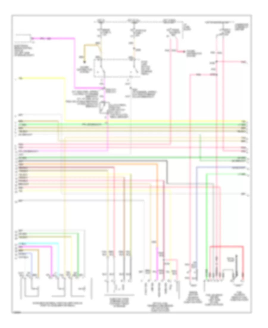
6.5L VIN F, Engine Performance Wiring Diagrams (4 of 4) for Chevrolet Pickup C3500 2000
List of elements for 6.5L VIN F, Engine Performance Wiring Diagrams (4 of 4) for Chevrolet Pickup C3500 2000:
- "serv eng soon" ind
- "serv throttle soon" ind
- (engine harness, approx 13 cm into ebcm breakout)
- (on fuel manager/filter) fuel heater
- 12v battery (fused)
- 12v battery fused
- 3/2 ctrl out
- A/c enable
- A/c system
- C10
- C11
- C12
- C13
- C14
- C15
- C16
- D10
- D11
- D12
- D13
- D14
- D15
- D16
- Data link connector (dlc) (under left side of dash, left of steering column)
- Eng-i k7
- Engine shutoff sol out
- Fuel sol module (5 vref)
- Fuel sol module feed
- Fuse 20a
- Fusible link
- G117 (top rear of right cylinder head)
- Glow plug 1
- Glow plug 2
- Glow plug 3
- Glow plug 4
- Glow plug 5
- Glow plug 6
- Glow plug 7
- Glow plug 8
- Glow plug output
- Glow plug relay (top left rear of engine)
- Grd
- Hot at all times
- Hot in run or start
- Ign
- Ignition
- Nca
- Pcm gnd
- Pnk
- Powertrain control module (pcm) (behind right side of dash, near blower motor)
- Red
- Relay ctrl
- S103
- S108
- S137
- S138
- S147
- S150
- S191
- S269
- Serial data sig
- Shift sol a input
- Shift sol b input
- Tan
- Tps 2 ref voltage
- Underhood fuse/relay center
- Wait to start ind
- Wastegate sol
- Wastegate solenoid (top left rear of engine)
7.4L
7.4L VIN J, Engine Performance Wiring Diagrams (1 of 4) for Chevrolet Pickup C3500 2000
List of elements for 7.4L VIN J, Engine Performance Wiring Diagrams (1 of 4) for Chevrolet Pickup C3500 2000:
- (19 cm into oxygen sensor harn)
- (attached to right rear of throttle body) idle air control (iac) valve
- (bottom front of engine near, crank pulley) crankshaft position sensor
- (top right side of engine) evaporative emission canister purge solenoid valve
- 1-2 shift sol ctrl
- 2-3 shift sol ctrl
- A/t w/ 4wd
- Air pump rel ctrl
- Cam posit sens sig
- Camshaft position sensor (inside distributor)
- Crank posit sens sig
- Ect sens sig
- Egr posit sig
- Fuel gauge lvl
- Fuel level input
- Fuel tank press sens
- G119 (right front side of eng block)
- Heated oxygen sensor (bank 1 sensor 1) (in left exhaust pipe in front of catalytic converter)
- Heated oxygen sensor (bank 2 sensor 1) (in right exhaust pipe in front of catalytic converter)
- Heated oxygen sensor (bank 2 sensor 2) (in right exhaust pipe in back of catalytic converter) (california)
- Ho2s low
- Ho2s sig
- Iat sens sig
- Idle air ctrl (iac) a hi
- Idle air ctrl (iac) b lo
- Ign feed
- Inj 1 ctrl
- Inj 2 ctrl
- Inj 3 ctrl
- Inj 4 ctrl
- Inj 5 ctrl
- Inj 6 ctrl
- Inj 7 ctrl
- Inj 8 ctrl
- Inline gender adapter
- Knock sens sig
- Knock sensor (ks) (left) (left side of engine block, below exhaust manifold)
- Knock sensor (ks) (right) (right side of engine block, below exhaust manifold)
- Map sens input
- Mass air flow sens sig
- Nca
- Others
- Pnk
- Pnk c ignition feed
- Pnk pnk
- Pnk pnk pnk pnk
- S114
- S148
- S149
- S162
- Sens rtn
- Sens sig
- Sensor return
- Tan
- Tcc pwm sol ctrl
- Temp sens input
- Throttle posit sens
- Vehicle control module (vcm) (left side of engine compt)
- Vehicle speed sensor (left side of transmission, left side of transfer case w/ 4wd)
- Vent ctlr
- Vss rtn
- Vss sig
- Vss signal
- W/ dual fuel tanks
7.4L VIN J, Engine Performance Wiring Diagrams (2 of 4) for Chevrolet Pickup C3500 2000
List of elements for 7.4L VIN J, Engine Performance Wiring Diagrams (2 of 4) for Chevrolet Pickup C3500 2000:
- 2-3 shift red
- Air injection reaction pump clutch (on front of air pump)
- Air injection reaction relay (underhood fuse/ relay center)
- Automatic transmission
- Automatic transmission fluid pressure (tfp) manual valve position switch
- Ecm1 fuse 20a
- Eng1 k7
- Evaporative emissions (evap) purge solenoid vacuum switch (on top of engine) (california)
- Exhaust gas recirculation (egr) valve (on top left side of eng)
- Fluid temperature sensor
- Fuel inj 1
- Fuel inj 2
- Fuel inj 3
- Fuel inj 4
- Fuel inj 5
- Fuel inj 6
- Fuel inj 7
- Fuel inj 8
- Fuse 20a l8
- G119 (right front side of eng block)
- Heated oxygen sensor (bank 1 sensor 2) (in left exhaust pipe in back of catalytic converter) (california)
- Hot in run & start
- Nca
- Pnk
- Pnk pnk pnk pnk
- Pnk pnk pnk tan red
- Pressure control solenoid valve
- Red
- S104
- S108
- S147
- S154
- S155
- Solenoid
- Tan
- Torque convertor clutch pulse width modulation solenoid
- Underhood fuse/relay center
7.4L VIN J, Engine Performance Wiring Diagrams (3 of 4) for Chevrolet Pickup C3500 2000
List of elements for 7.4L VIN J, Engine Performance Wiring Diagrams (3 of 4) for Chevrolet Pickup C3500 2000:
- (eng harn,
- (eng harn, approx 4 cm from egr valve breakout)
- (engine harn)
- (inside left frame rail, near rear crossmember)
- (inside left frame rail, near rear crossmember) g415
- (taillamp extension harness, approx 10 cm from fuel pump balance module breakout)
- 7 cm from egr valve breakout) s106
- Automatic transmission input shaft speed sensor (left side of transmission)
- Aux tank fuel lvl sig
- Auxiliary fuel tank level sensor (in fuel tank)
- Balance fuel pump (on inside left frame rail, near front of rear tank)
- Convenience center (under left side of dash)
- D w/ dual fuel tanks
- Engine coolant temperature sensor (top right front of engine, near thermostat housing)
- F7 ign e fuse 10a g8
- Fuel gauge input
- Fuel pump & sender (w/o dual fuel tanks) (in fuel tank)
- Fuel pump balance module (inside left side of frame rail)
- Fuel pump balance relay (on fuel pump balance module)
- Fuel pump module (w/ dual fuel tanks)
- Fuel tank pressure sensor (in fuel tank) (california)
- Fuel tanks
- G117 (back side of eng block, below right side of cylinder head)
- G415
- Gauges fuse 4 10a
- Ground
- Hot in off, run or start
- Hot in run or start
- I/p fuse block
- Ignition
- Instrument cluster
- Intake air temperature sensor (in air intake duct)
- Manifold absolute pressure (map) sensor (top right front of engine)
- Mass air- flow sensor (in air intake duct)
- Output to gauge c2
- Pnk
- Pnk a
- Pnk pnk tan red
- Primary tank fuel lvl sig
- Relay ctrl
- S103
- S146
- S213
- S231
- S232
- S315
- S318
- S319
- S324
- S430
- Service engine soon indicator
- Speedometer input
- Tachometer input
- Tan a
- Throttle position sensor (on throttle body assembly)
- Trans fuse 20 10a
- Underhood fuse/relay center
- W/ dual fuel tank
- W/ dual w/o dual fuel tank
- W/o dual fuel tank
- W/o dual fuel tanks
7.4L VIN J, Engine Performance Wiring Diagrams (4 of 4) for Chevrolet Pickup C3500 2000
List of elements for 7.4L VIN J, Engine Performance Wiring Diagrams (4 of 4) for Chevrolet Pickup C3500 2000:
- (back side of eng block, below right side of cylinder head)
- (engine harness, approx 13 cm from s150
- (engine harness, approx 7 cm from ebcm breakout)
- (i/p harn, 13 cm from ccm)
- (i/p harn, 20 cm from inflatable restraint switch breakout)
- (i/p harness, approx 40 cm from instrument cluster breakout)
- (or
- 4wd input
- 5v ref voltage
- 87a
- A/c comp enable rel
- A/c request signal
- A/t
- Air conditioning system
- Air inlet vlv mtr ctlr
- Automatic 4wd
- Automatic transfer case controller
- Aux fan relay
- Brake sw input
- Brake switch input
- Check eng lp ctrl
- Clutch pedal position (cpp) switch (at top of clutch pedal bracket)
- Cooling fans system
- Cpp sw input
- Cruise control module (left rear of engine compt, on firewall)
- Cruise ctrl sig eng
- Data link connector (under left side of dash, left side of steering column)
- Distributor
- Dual fuel mod return
- Ebcm breakout)
- Egr vlv feed
- Egr vlv ground
- Electronic brake control module (ebcm) (on left side of engine compt)
- Electronic variable orifice/ passlock control module (center of dash)
- Est output sig
- Evap can purge vlv
- F11 ecmb fuse 20a
- Force motor feed
- Force motor return
- Four whl dr sig
- Four whl dr sig lo
- Fuel level input
- Fuel pump a prime connector (left rear of eng compt)
- Fuel pump relay
- Fuel pump rly ctrl
- G117
- G12
- Ground
- High voltage coil wire
- Hot at all times
- Hot in run
- I/p fuse block
- Ign coil out
- Ign input
- Ign timing sig.
- Ignition
- Ignition coil
- Ignition control module (on rear of intake manifold)
- Ignition feed
- M/t
- M4 brake fuse 18 10a n3
- Manual or selectable 4wd
- Pnk
- Pnk a
- Pressure switch input
- Radio
- Red
- S101
- S103
- S111 (engine harness, approx 7 cm from ebcm breakout)
- S151
- S152
- S153
- S221
- Sensor ground
- Sensor return
- Serial data sig
- Speed sensor
- Speed sensor input
- Stoplamp switch (top of brake pedal)
- Stoplamp/ clutch switch input
- Switch signal
- Trans input speed rtn
- Trans input speed sig
- Transfer case control module (under dash, on steering column support bracket)
- Transfer case switch (left top of transfer case)
- Transmissions system
- Underhood fuse/ relay center
- Vcm sig
- Vehicle control module (vcm) (left side of engine compt)
- Vss input
- Vss sig out