ENGINE PERFORMANCE
2.8L
2.8L, Engine Performance Wiring Diagrams (1 of 3) for Mercedes-Benz C280 1999

List of elements for 2.8L, Engine Performance Wiring Diagrams (1 of 3) for Mercedes-Benz C280 1999:
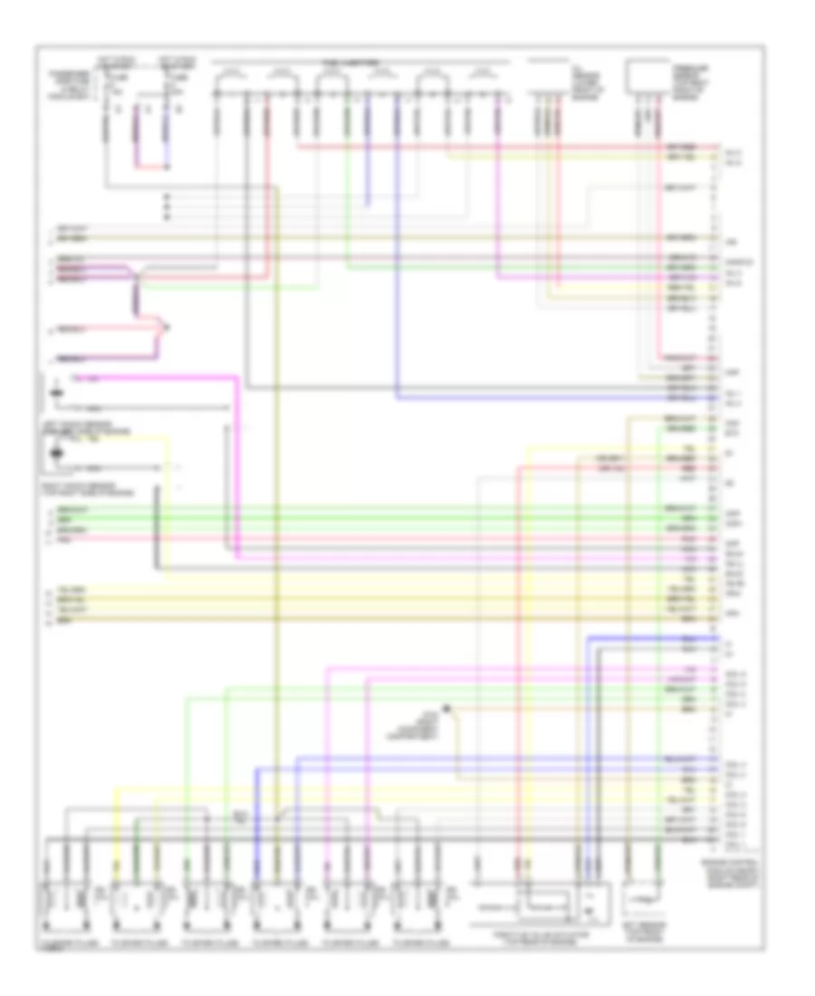
2.8L, Engine Performance Wiring Diagrams (2 of 3) for Mercedes-Benz C280 1999
List of elements for 2.8L, Engine Performance Wiring Diagrams (2 of 3) for Mercedes-Benz C280 1999:
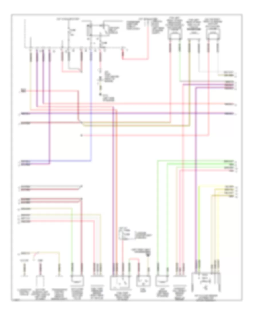
2.8L, Engine Performance Wiring Diagrams (3 of 3) for Mercedes-Benz C280 1999
List of elements for 2.8L, Engine Performance Wiring Diagrams (3 of 3) for Mercedes-Benz C280 1999: