ENGINE PERFORMANCE
3.0L TURBO DIESEL
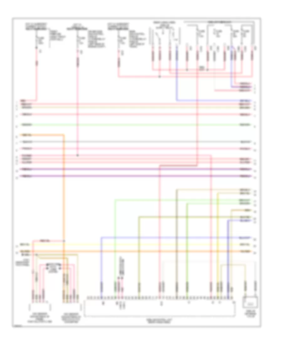
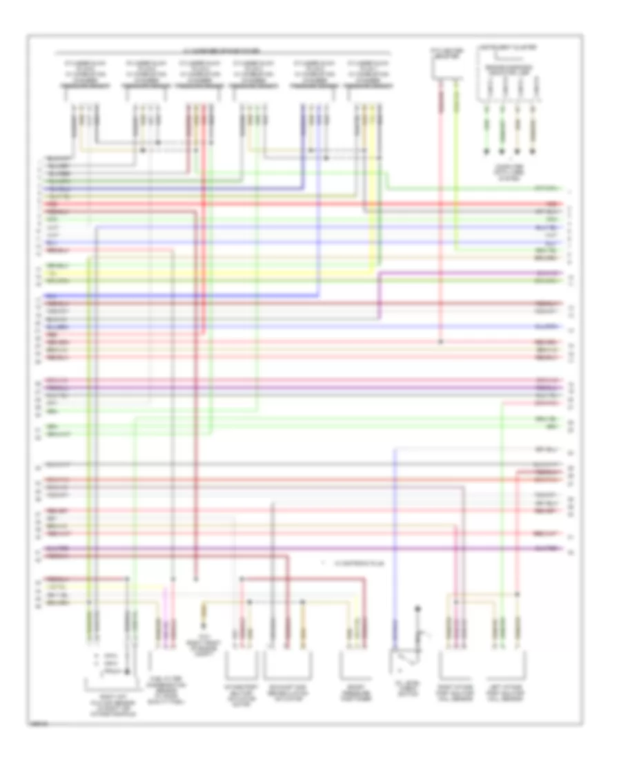
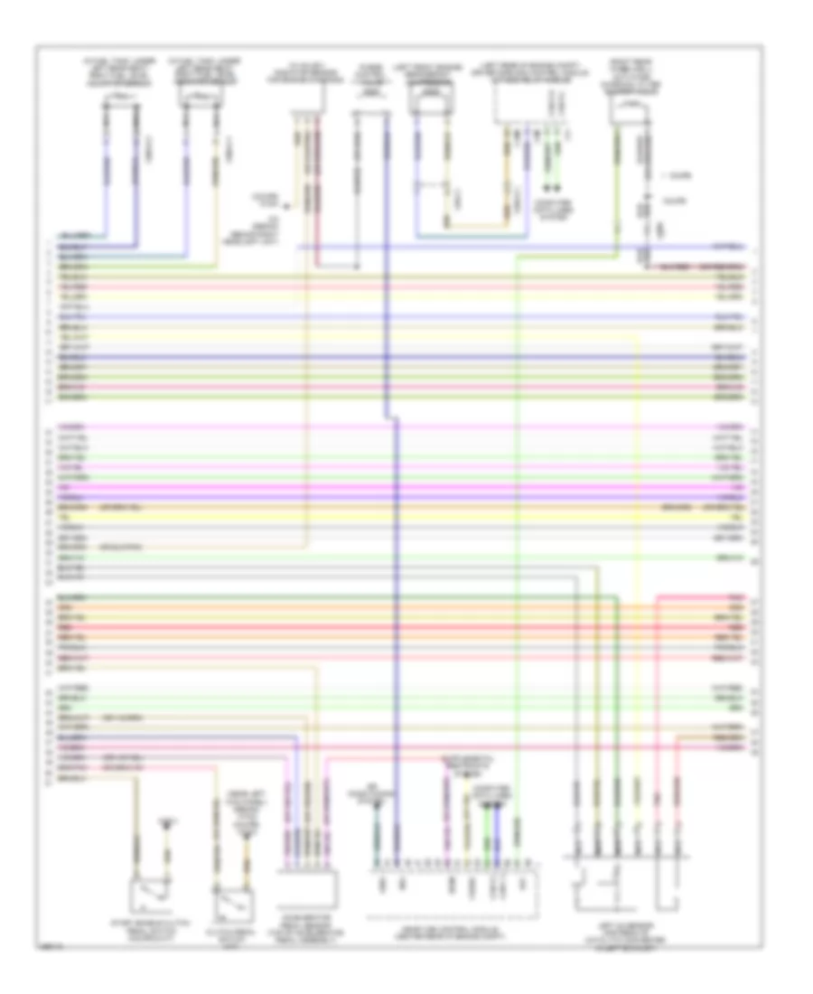
3.0L Turbo Diesel, Engine Performance Wiring Diagram (1 of 7) for Mercedes-Benz E350 BlueTEC 2011

List of elements for 3.0L Turbo Diesel, Engine Performance Wiring Diagram (1 of 7) for Mercedes-Benz E350 BlueTEC 2011:
- (-)
- 30z
- 87m
- Accelerator pedal sensor (top of accelerator pedal assembly)
- Air conditioning system
- C1v
- C3i
- C3m
- C4i
- C6i
- C7i
- C8s
- C9i
- Can c h
- Can c l
- Can e h
- Can e l
- Cdi control module (left rear of engine compt)
- Clutch pedal switch
- Computer data lines system
- Control unit
- Crash
- Differential pressure sensor/diesel particulate filter for onboard diagnostics (obd)
- Driver side sam control module w/ fuse/relay module (left rear of engine compt)
- Ekp
- Engine circuit relay
- Front prefuse (right front footwell)
- Fuel pump relay
- Fuse 150a
- Fuse 15a
- Fuse 20a
- Fuse 25a
- Fuse 7.5a
- Hot at all times
- Hot w/ chassis circuit 87 relay energized
- Hot w/ circuit 15 relay energized
- Kup1
- Left fuel level indicator sensor (in fuel tank, under left rear seat)
- Lues
- Nca
- Pnk
- Pnk/red
- Rear sam control module w/ fuse/ relay module (left side of trunk)
- Red
- Right fuel level indicator sensor (in fuel tank, under right rear seat)
- Sig
- Sp1m
- Sp1s
- Sp2m
- Sp2s
- Starting/charging system
- Str
- Temperature sensor upstream of diesel particulate filter
- Temperature sensor upstream of scr catalytic converter
- U pwg
- W/ fuel pump
- W/o fuel pump control unit
- W15/2 (near left kick panel)
- W3/1 (right front of engine compt)
- X26-c1
- X36/3-c1
- X36/3-c2
- X86/1-c1b
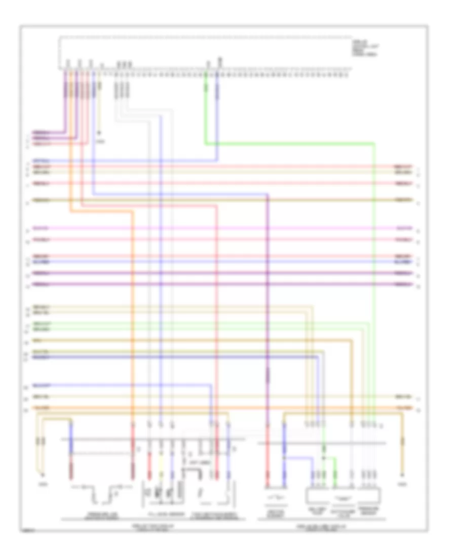
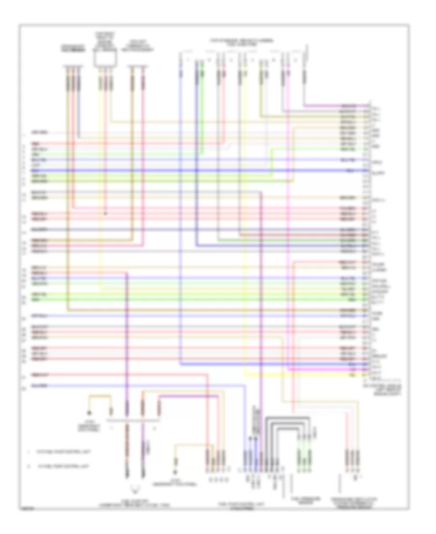
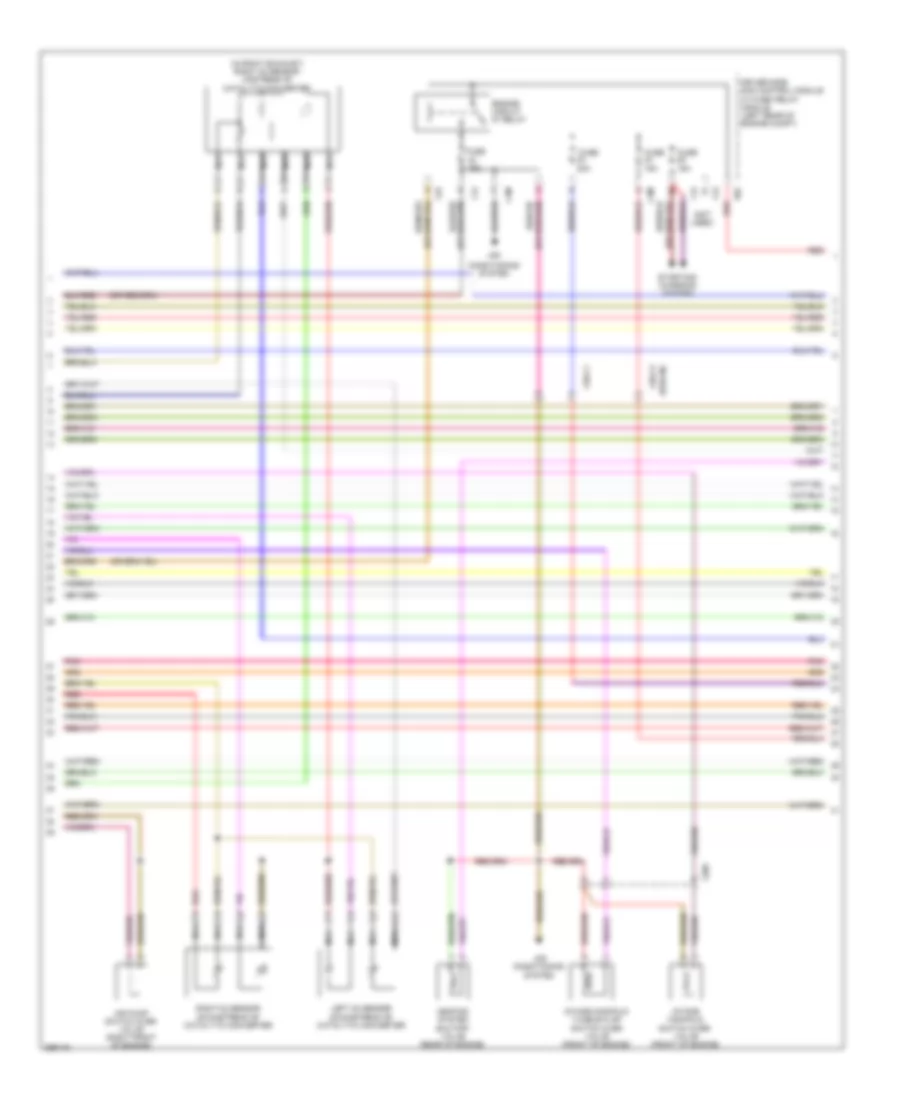
3.0L Turbo Diesel, Engine Performance Wiring Diagram (2 of 7) for Mercedes-Benz E350 BlueTEC 2011
List of elements for 3.0L Turbo Diesel, Engine Performance Wiring Diagram (2 of 7) for Mercedes-Benz E350 BlueTEC 2011:
- (-)
- 15 r
- C19a
- C20a
- C21a
- C22a
- C6i
- Can i h
- Can i l
- Computer data lines system
- Driver side sam control module w/ fuse/relay module (left rear of engine compt)
- E19
- E20
- E21
- E22
- Front prefuse (right front footwell)
- Fuse 10a
- Fuse 150a
- Fuse 15a
- Fuse 20a
- Fuse 5a
- Fuse 7.5a
- Hot w/ circuit 15 relay energized
- Hot w/ quiescent current cutout relay energized
- Ig1
- Lines system computer data
- Nox sensor downstream of diesel particulate filter
- Nox sensor downstream of scr catalytic converter
- Pnk
- Pnk/red
- Rear sam control module w/ fuse/relay module (left side of trunk)
- Red
- Scr
- Sig
- W15/1 (near right kick panel)
- X86/1-c1a
- X86/1-c2
3.0L Turbo Diesel, Engine Performance Wiring Diagram (3 of 7) for Mercedes-Benz E350 BlueTEC 2011
List of elements for 3.0L Turbo Diesel, Engine Performance Wiring Diagram (3 of 7) for Mercedes-Benz E350 BlueTEC 2011:
- (not used)
- +5v
- 15 r
- Delivery pump
- Empty
- Fill level sensor
- Full
- Heating element
- Pressure line heating element
- Pressure sensor
- Red
- Reserve
- Sig
- Sp2m
- Switchover valve
- Tank heating element & temperature sensor
- W8/8
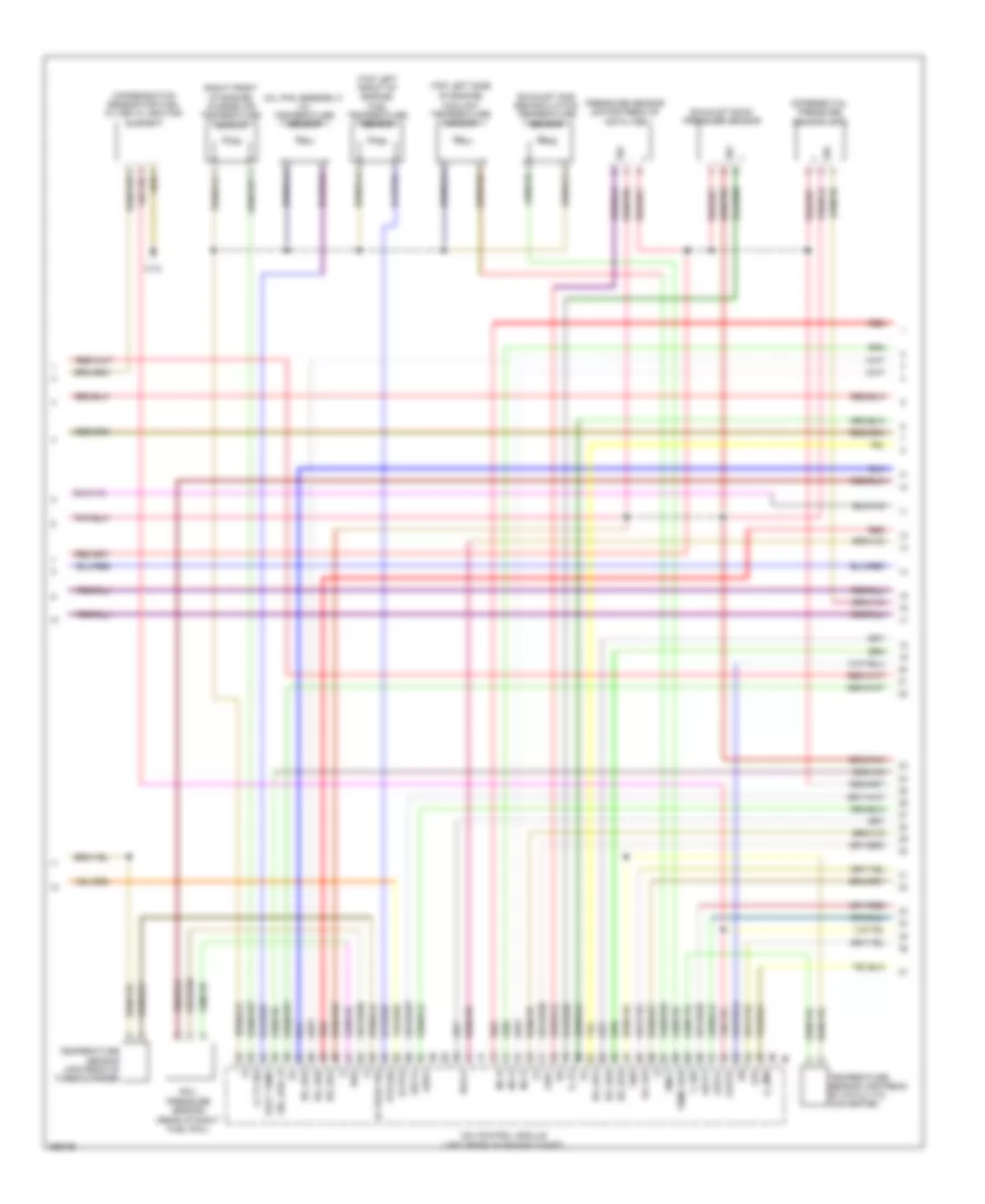
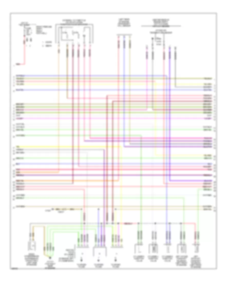
3.0L Turbo Diesel, Engine Performance Wiring Diagram (4 of 7) for Mercedes-Benz E350 BlueTEC 2011
List of elements for 3.0L Turbo Diesel, Engine Performance Wiring Diagram (4 of 7) for Mercedes-Benz E350 BlueTEC 2011:
- (+)
- (-)
- (oil pan assembly) oil temperature sensor
- (right front of engine) charge air temperature sensor
- (top left front of engine) fuel temperature sensor
- (top left side of engine)
- A_zme
- Br_ds1
- Br_ds2
- Br_ds3
- Br_ds4
- Br_ds5
- Br_ds6
- Cdi control module (left rear of engine compt)
- Condensation sensor for fuel filter w/ heating element
- Coolant temperature sensor
- Differential pressure sensor (dpf)
- Ea lds
- Eka-a
- Exhaust back pressure sensor
- Exhaust gas recirculation temperature sensor
- Exts2
- E_p3
- Flwtr
- Gnd
- Ia tegr pre
- Inj h
- Kts sig
- Ldr
- Ll tf sig
- Lsca1
- Lscp1
- Lsh1
- Lsvg1
- Lsw1
- Oelt temp
- Pressure sensor downstream of air filter
- Rail pressure sensor (rear of right fuel rail)
- Rds
- Red
- Sig
- Sig_kas_r
- Temp agr
- Temperature sensor upstream of catalytic converter
- Temperature sensor upstream of turbocharger
- Tmot
- T_sig
- W12
3.0L Turbo Diesel, Engine Performance Wiring Diagram (5 of 7) for Mercedes-Benz E350 BlueTEC 2011
List of elements for 3.0L Turbo Diesel, Engine Performance Wiring Diagram (5 of 7) for Mercedes-Benz E350 BlueTEC 2011:
- Boost pressure sensor
- Cylinder glow plug 1
- Cylinder glow plug 2
- Cylinder glow plug 3
- Cylinder glow plug 4
- Cylinder glow plug 5
- Cylinder glow plug 6
- Exhaust gas recirculation cooling bypass flap hall sensor
- Glow output stage
- Left hot film maf sensor (in left air intake manifold)
- Nca
- Oxygen sensor upstream of catalytic converter
- Pressure regulator valve
- Quantity control valve
- Red
- Starting/ charging system
- Throttle valve actuator
- W/ increased engine power
- W/o increased engine power
- W11
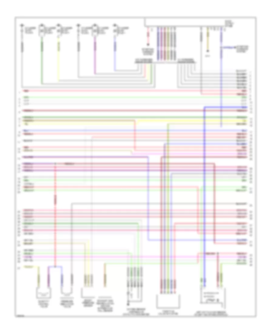
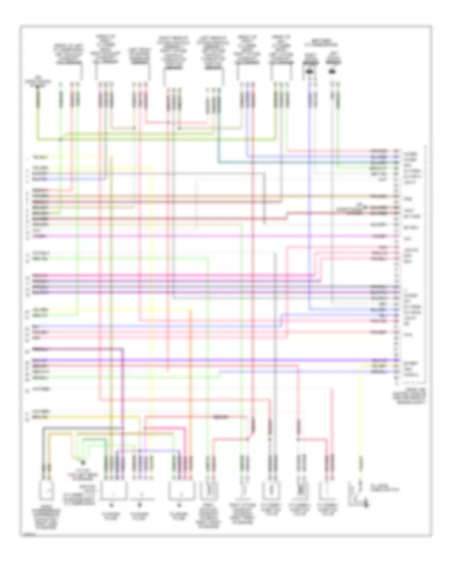
3.0L Turbo Diesel, Engine Performance Wiring Diagram (6 of 7) for Mercedes-Benz E350 BlueTEC 2011
List of elements for 3.0L Turbo Diesel, Engine Performance Wiring Diagram (6 of 7) for Mercedes-Benz E350 BlueTEC 2011:
- Boost pressure positioner
- Can b h
- Can b l
- Can e h
- Can e l
- Computer data lines system
- Cylinder glow plug 1 w/ combustion chamber pressure sensor
- Cylinder glow plug 2 w/ combustion chamber pressure sensor
- Cylinder glow plug 3 w/ combustion chamber pressure sensor
- Cylinder glow plug 4 w/ combustion chamber pressure sensor
- Cylinder glow plug 5 w/ combustion chamber pressure sensor
- Cylinder glow plug 6 w/ combustion chamber pressure sensor
- Engine daignosis indicator lamp
- Exhaust gas recirculation actuator
- Fuel filter condensation sensor (w/ poor quality fuel)
- Instrument cluster
- Intake port shutoff actuator motor
- Left intake port shutoff hall sensor
- Nca
- Oil level check switch
- Ptc heater booster
- Red
- Right hot film maf sensor (in right air intake manifold)
- Right intake port shutoff hall sensor
- W/ distronic plus
- W/ increased engine power
- W3/1 (right front of engine compt)
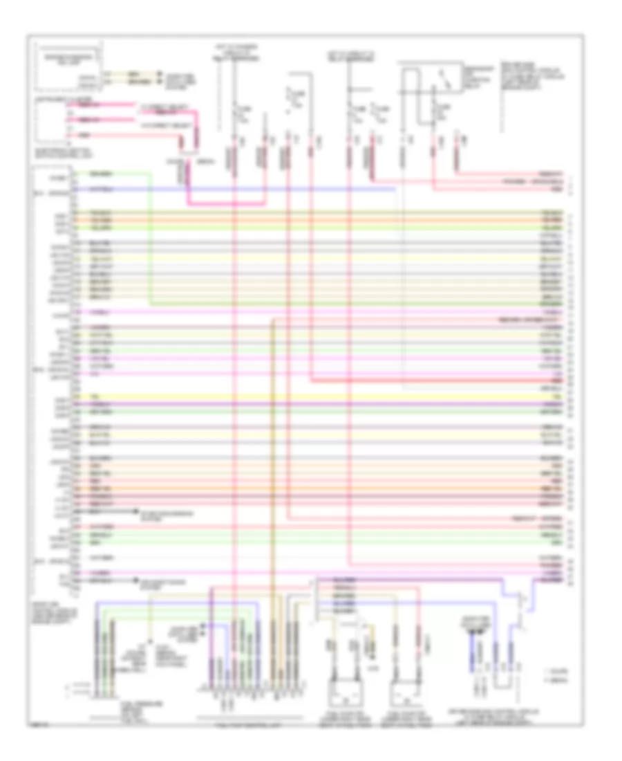
3.0L Turbo Diesel, Engine Performance Wiring Diagram (7 of 7) for Mercedes-Benz E350 BlueTEC 2011
List of elements for 3.0L Turbo Diesel, Engine Performance Wiring Diagram (7 of 7) for Mercedes-Benz E350 BlueTEC 2011:
- (+)
- (-)
- (near right kick panel)
- (top of engine, above cylinders) fuel injectors
- (top right front of engine) camshaft hall sensor
- Can c h
- Can c l
- Cdi control module (left rear of engine compt)
- Coolant thermostat heating element
- Crankcase ventilation system differential pressure sensor
- Crankshaft hall sensor
- Drv
- Ekp
- Erg_sig
- E_hfm1
- E_t1-1
- E_t1-2
- Fuel pressure sensor
- Fuel pump (fp) (under right rear seat,in fuel tank)
- Fuel pump control unit (if equipped)
- Gnd
- Hfm-2
- Ia pfdp1
- Inj h
- Inj l
- Kds_sig
- Kg_sig
- Kwga
- Lines system computer data
- M (+)
- M (-)
- Nca
- Nwg_sig
- Oss
- Poti (+)
- Poti (-)
- Poti sig
- Red
- Sig
- Sig_kas_l
- W/ fuel pump control unit
- W/o fuel pump control unit
- W15/1
- W15/1 (near right kick panel)
- X26-c3
- X36/2-c1
3.5L
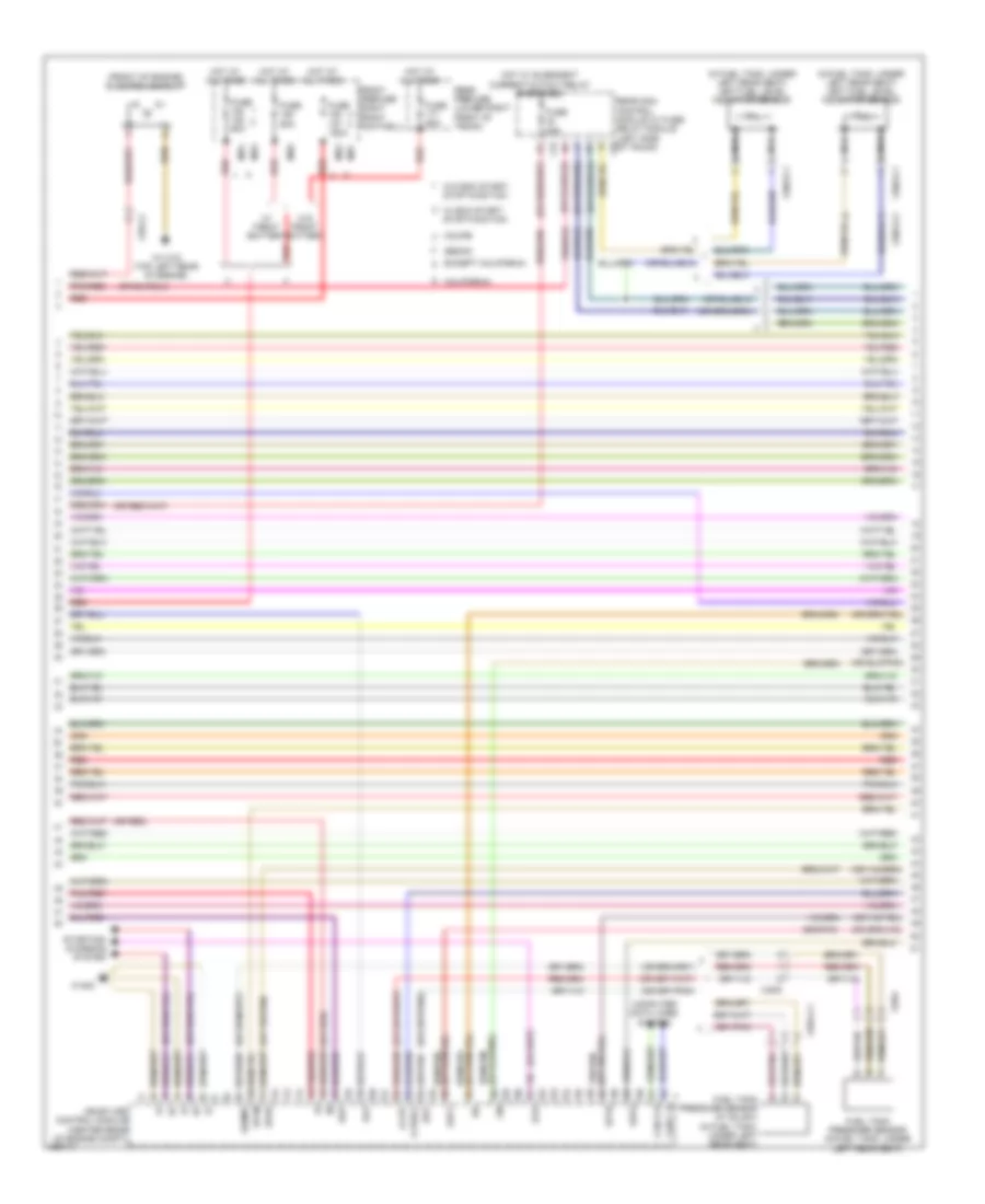
3.5L, Engine Performance Wiring Diagram (1 of 6) for Mercedes-Benz E350 BlueTEC 2011
List of elements for 3.5L, Engine Performance Wiring Diagram (1 of 6) for Mercedes-Benz E350 BlueTEC 2011:
- (+)
- (+) sv
- (-)
- (or ev2)
- (or ev5)
- (or ev6)
- (or red)
- 30g
- A s dk
- Air conditioning system
- C12s
- C16s
- C2i
- C3m
- C4i
- C5c
- C6i
- C7i
- C9g
- Can b h
- Can b l
- Can c h
- Can c l
- Computer data lines system
- Coupe
- Driver side sam control module w/ fuse/ relay module (left rear of engine compt)
- Electronic ignition switch control unit
- Engine diagnosis ind lamp
- Ev1
- Ev2
- Ev3
- Ev4
- Ev5
- Ev6
- Fuel pressure sensor (on left fuel rail)
- Fuel pump (fp) (under right rear seat, in fuel tank)
- Fuel pump control unit
- Fuse 10a
- Fuse 40a
- Fuse 7.5a
- Hot w/ chassis circuit 87 relay energized
- Hot w/ circuit 15 relay energized
- Instrument cluster
- Ipm
- Lin c1
- Ls2hk
- Lsh1hk
- Lsh2hk
- Lshk
- Lshvk1
- Lsik
- Lsu1un
- Lsu1vm
- Lsu2ia
- Lsu2ip
- Lsu2un
- Lsu2vm
- Me-sfi (me) control module (center rear of engine compt)
- Mr hfm1
- Nca
- Nwae2
- Nwg m
- Nwg m2
- Nwga1
- Nwsa 1
- Nwse 1
- Nwse 2
- Pnk/red
- Red
- Secondary air injection relay
- Sedan
- Sig
- Slv
- Starting/charging system
- Suv1
- Ths
- W/ direct select
- W/o direct select
- W15/1 (sedan) (near right kick panel)
- W7 (coupe) (on right rear wheelwell)
- W76
- X36/2-c1
- X36/3-c2
- Zue 1
- Zue 3
- Zue 4
- Zue 5
- Zue 6
- Zuf 2
3.5L, Engine Performance Wiring Diagram (2 of 6) for Mercedes-Benz E350 BlueTEC 2011
List of elements for 3.5L, Engine Performance Wiring Diagram (2 of 6) for Mercedes-Benz E350 BlueTEC 2011:
- (+) sv
- (front of engine) electric air pump
- (in fuel tank, under left rear seat) left fuel level indicator sensor
- (or red)
- C3i
- C9i
- California
- Can c h
- Can e h
- Computer data lines system
- Coupe
- Dst
- Ekp
- Except california
- Front prefuse (right front footwell)
- Fuel tank pressure sensor (in fuel tank, under left rear seat)
- Fuel tank pressure sensor (w/ sulev) (in fuel tank, under left rear seat)
- Fuse 150a
- Fuse 25a
- Fuse 60a
- Hot at all times
- Hot w/ quiescent current cutout relay energized
- Kup1
- Kup2
- Lin
- Me-sfi (me) control module (center rear of engine compt)
- Mr2
- Mr3
- Mr4
- Mr6
- Mr7
- Nca
- Pnk/red
- Rear prefuse (lower right front of trunk)
- Rear sam control module w/ fuse/ relay module (left side of trunk)
- Red
- Sedan
- Senm1
- Slp
- Sp1m
- Sp1s
- Sp2s
- Starting/ charging system
- Str
- U pwg1
- W/ eco start/ stop function
- W/ front battery
- W/o eco start/ stop function
- W/o front battery
- W11w2 (top left rear of engine)
- W16/5
- X25/4
- X25/4-c1
- X26-c2
- X35/6
- X36/3-c1
- X36/3-c2
3.5L, Engine Performance Wiring Diagram (3 of 6) for Mercedes-Benz E350 BlueTEC 2011
List of elements for 3.5L, Engine Performance Wiring Diagram (3 of 6) for Mercedes-Benz E350 BlueTEC 2011:
- (coupe) w16/4
- (in fuel tank, under left rear seat) right fuel level indicator sensor
- (left front engine) refrigerant compressor
- (left rear of engine compt) driver side sam control module w/ fuse/ relay module
- (near left kick panel) (sedan) w15/2 (coupe) w16/3
- (or red)
- (right rear wheelwell) activated charcoal filter shutoff valve
- (w/ sulev) radiator sensor for engine diagnosis
- Aav
- Accelerator pedal sensor (top of accelerator pedal assembly)
- Air conditioning system
- C18m
- C3m
- C7i
- Can c l
- Can e h
- Can e l
- Clutch pedal switch (m/t)
- Computer data lines system
- Coupe
- Crash
- Left o2 sensor upstream of catalytic converter (in left exhaust)
- Lues
- Me-sfi (me) control module (center rear of engine compt)
- Nca
- Pnk
- Purge control valve
- Red
- Reg
- Sp2m
- Start enable clutch pedal switch (coupe & m/t)
- W16/3
- W2 (sedan) (behind right headlight unit)
- X25/2-c1
- X26-c1
- X35/6
- X36/2-c1
- X36/3-c2
3.5L, Engine Performance Wiring Diagram (4 of 6) for Mercedes-Benz E350 BlueTEC 2011
List of elements for 3.5L, Engine Performance Wiring Diagram (4 of 6) for Mercedes-Benz E350 BlueTEC 2011:
- (in right exhaust) right o2 sensor upstream of catalytic converter
- (not used)
- (sedan)
- 16s
- Air
- Air conditioning system
- Air pump switch over valve (right front of engine)
- C2i
- C3m
- C4i
- C4m
- C6i
- Conditioning system
- Driver side sam control module w/ fuse/ relay module (left rear of engine compt)
- Engine circuit 87 relay
- Fuse 15a
- Fuse 20a
- Heating system shutoff valve (rear of engine)
- Intake manifold switch over valve (front of engine)
- Intake manifold tumble flap switch over valve (front of engine)
- Left o2 sensor downstream of catalytic converter
- Nca
- Pnk
- Red
- Right o2 sensor downstream of catalytic converter
- Starting/ charging system
- X205
- X26-c1
- X26-c2
3.5L, Engine Performance Wiring Diagram (5 of 6) for Mercedes-Benz E350 BlueTEC 2011
List of elements for 3.5L, Engine Performance Wiring Diagram (5 of 6) for Mercedes-Benz E350 BlueTEC 2011:
- (center rear of engine compt) hot film mass air flow sensor
- (integral to throttle valve actuator) throttle valve actuator
- (left rear of engine) crankshaft hall sensor
- Coupe
- Cylinder 4 injection valve
- Cylinder 5 injection valve
- Cylinder 6 injection valve
- Front prefuse (right front footwell)
- Fuse 150a
- Hot at all times
- Ignition coils (cylinder 4, 5, 6: on engine left cylinder bank)
- Intake air temperature sensor
- Left exhaust camshaft solenoid (left front of engine)
- Left intake camshaft solenoid (left front of engine)
- Mr2
- Mr7
- Pnk
- Radio interference suppression capacitor 2 (left side of engine)
- Red
- Sedan
- To spark plugs
- W11w1 (top right rear of engine)
- W16/5
- X26-c1
3.5L, Engine Performance Wiring Diagram (6 of 6) for Mercedes-Benz E350 BlueTEC 2011
List of elements for 3.5L, Engine Performance Wiring Diagram (6 of 6) for Mercedes-Benz E350 BlueTEC 2011:
- (-)
- (between cylinder banks)
- (front of left cylinder bank) left exhaust camshaft hall sensor
- (front of left cylinder bank) left intake camshaft hall sensor
- (front of right cylinder bank) right exhaust camshaft hall sensor
- (front of right cylinder bank) right intake camshaft hall sensor
- (left front of engine) pressure sensor
- (left rear of intake manifold assembly) left intake manifold tumble flap position sensor
- (right rear of intake manifold assembly) right intake manifold tumble flap position sensor
- Air conditioning system
- Cylinder 1 injection valve
- Cylinder 2 injection valve
- Cylinder 3 injection valve
- Dcm
- Dcp
- Dk1
- Dk2
- E a ks1a
- E a ks1b
- E a ks2a
- E a ks2b
- Ea tans
- Ef hfm1
- Ef ref1
- Hav
- Ignition coils (cylinder 1, 2, 3: on engine right cylinder bank)
- Ip1s
- Ip2s
- Kwdga
- Left knock sensor
- Lshvk2
- Lsu1a
- Lsu1p
- Me-sfi (me) control module (center rear of engine compt)
- Nwge1
- Nwge2
- Nwsa 2
- Oil level check switch
- Oss
- Pnk
- Radio interference suppression capacitor 1 (right side of engine)
- Right exhaust camshaft solenoid (right front of engine)
- Right intake camshaft solenoid (right front of engine)
- Right knock sensor
- Tmot
- To spark plugs
- W11w2 (top left rear of engine)