ENGINE PERFORMANCE
3.5L
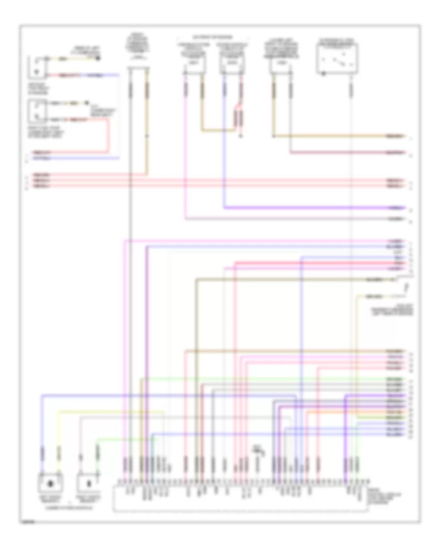
3.5L, Engine Performance Wiring Diagram (1 of 4) for Mercedes-Benz ML350 2007

List of elements for 3.5L, Engine Performance Wiring Diagram (1 of 4) for Mercedes-Benz ML350 2007:
- (in right rear wheelwell)
- Accelerator pedal sensor (top of accelerator pedal assembly)
- Activated charcoal filter shutoff valve
- Air pump relay
- Akf
- Can-c h
- Can-c l
- Computer data lines system
- Electric suction fan engine & a/c w/ integrated control (behind radiator)
- Engine circuit 87 relay
- Engine compartment fuse & relay box (right side of engine compt)
- Fuel pump module relay
- Fuel tank pressure sensor (inside fuel tank)
- Fuse 10a
- Fuse 15a
- Fuse 20a
- Fuse 40a
- Fuse 5a
- Hot at all times
- Hot w/ circuit 15 relay energized
- Hot w/ starter relay energized
- Kpr
- Load compartment fuse & relay box (right rear of cargo area)
- Lues
- Me-sfi control module (top center of engine)
- Mr1
- Mr2
- Mr3
- Mr4
- Pnk
- Purge control valve (left side of engine compt)
- Restraints system control module (under center console)
- Slp
- Sp1m
- Sp1s
- Sp2m
- Sp2s
- Starting/charging system
- Usp1
- W16/3 (left rear of engine compt)
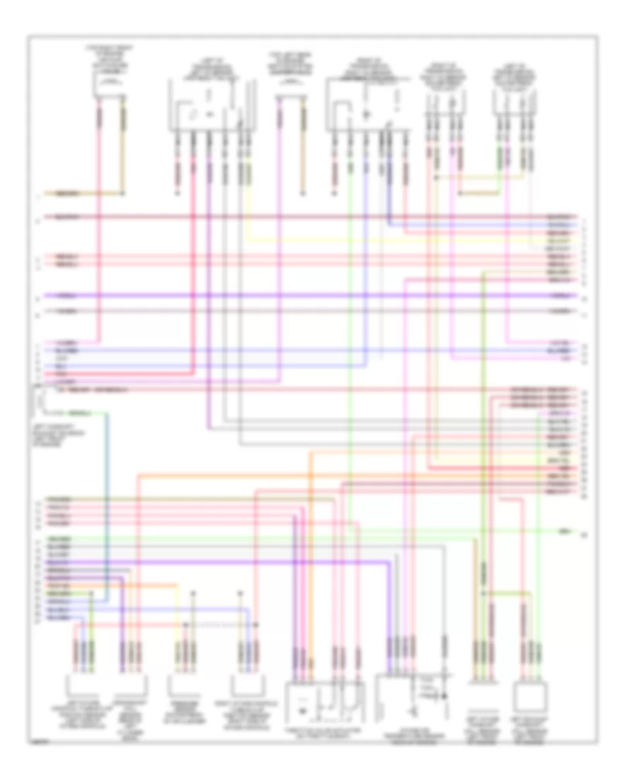
3.5L, Engine Performance Wiring Diagram (2 of 4) for Mercedes-Benz ML350 2007
List of elements for 3.5L, Engine Performance Wiring Diagram (2 of 4) for Mercedes-Benz ML350 2007:
- (-)
- (front of engine) three-disk thermostat valve
- (in engine oil pan) oil level switch
- (lower left front of engine) power steering pump pressure regulator valve
- (not used)
- (on front of engine)
- (rear of left cylinder bank) w11w2
- (under intake manifold)
- Air pump (top front of engine)
- Brs
- Coolant temperature sensor (left rear of engine)
- Dkp2
- Dk_s+
- Dk_s-
- Drs
- Hav
- Hfm
- Intake manifold tumble flap switchover valve
- Ks_m
- Ks_s
- Kwg
- Kws a2
- Left knock sensor 2
- Me-sfi control module (top center of engine)
- Nca
- Nwge1
- Nwge2
- Oss
- Pnk
- Right fuel pump (under right seat of 2nd seat row)
- Right knock sensor 1
- Slv
- Ths
- Tmot
- Tna
- Variable intake manifold switchover valve
- W17 (under right rear seat)
- X26
3.5L, Engine Performance Wiring Diagram (3 of 4) for Mercedes-Benz ML350 2007
List of elements for 3.5L, Engine Performance Wiring Diagram (3 of 4) for Mercedes-Benz ML350 2007:
- (left of transmission) left o2 sensor downstream twc (kat)
- (left of transmission) left o2 sensor upstream twc (kat)
- (right of transmission) right o2 sensor downstream twc (kat)
- (right of transmission) right o2 sensor upstream twc (kat)
- (top left rear of engine) heating system shutoff valve
- (top right front of engine) air pump switchover valve
- Crankshaft hall sensor (rear of left cylinder bank)
- Intake air temperature sensor (rear of engine)
- Left camshaft exhaust solenoid (left front of engine)
- Left exhaust camshaft hall sensor (left front of engine)
- Left intake camshaft hall sensor (left front of engine)
- Left intake manifold tumble flap position sensor (left side of intake manifold)
- Nca
- Pnk
- Pressure sensor downstream of air cleaner
- Red
- Right intake manifold tumble flap position sensor (right side of intake manifold)
- Throttle valve actuator (on throttle body)
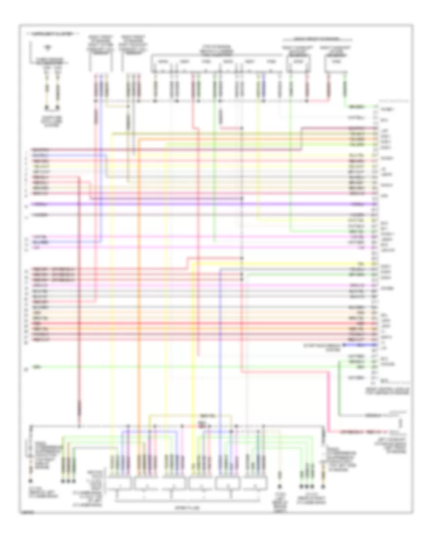
3.5L, Engine Performance Wiring Diagram (4 of 4) for Mercedes-Benz ML350 2007
List of elements for 3.5L, Engine Performance Wiring Diagram (4 of 4) for Mercedes-Benz ML350 2007:
- "check engine" mil indicator
- (+)
- (right front of engine)
- (right front of engine) right exhaust camshaft hall sensor
- (right front of engine) right intake camshaft hall sensor
- (top of engine, above cylinders) fuel injectors
- Can- b h
- Can- b l
- Computer data lines system
- Dkl
- Dkp m
- Ev1
- Ev2
- Ev3
- Ev4
- Ev5
- Hfm
- Ignition coils (1, 2, & 3: top of right cylinder bank) (4, 5 & 6: top of left cylinder bank)
- Instrument cluster
- Kwse 1
- Left camshaft intake solenoid (left front of engine)
- Lhp
- Lin
- Ls2hk
- Lsh1hk
- Lshk
- Me-sfi control module (top center of engine)
- Nwae2
- Nwg m
- Nwga1
- Nws e2
- Nwsa 1
- Radio interference suppression capacitor 1 (top right side of engine)
- Radio interference suppression capacitor 2 (top left side of engine)
- Red
- Right camshaft exhaust solenoid
- Right camshaft intake solenoid
- Spark plugs
- Starting/charging system
- W11w1 (rear of right cylinder bank)
- W11w2 (rear of left cylinder bank)
- W16/3 (left rear of engine compt)
- Zue 1
- Zue 2
- Zue 3
- Zue 4
- Zue 5
- Zue 6