ENGINE PERFORMANCE
3.0L TURBO DIESEL
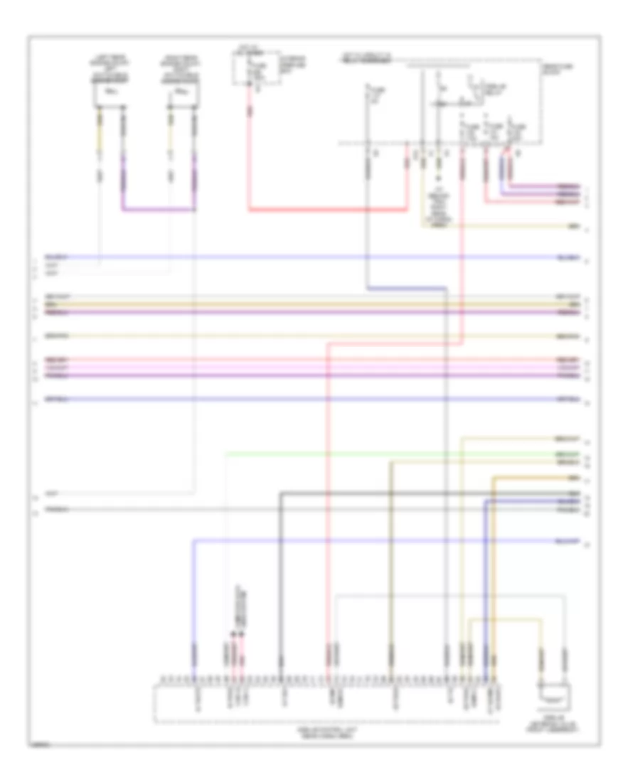
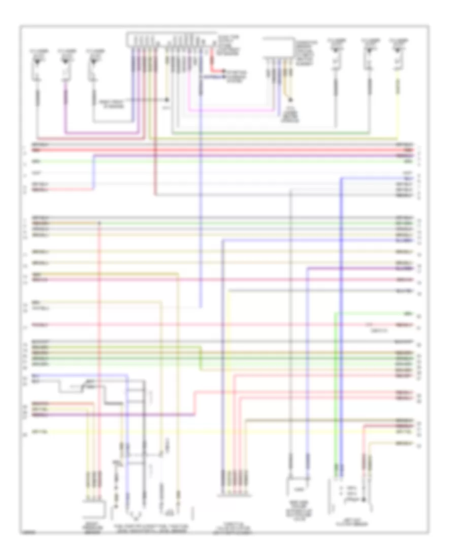
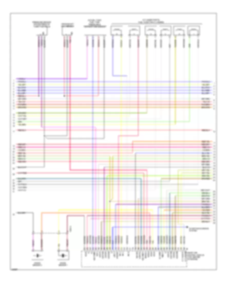
3.0L Turbo Diesel, Engine Performance Wiring Diagram (1 of 7) for Mercedes-Benz ML350 BlueTEC 2012

List of elements for 3.0L Turbo Diesel, Engine Performance Wiring Diagram (1 of 7) for Mercedes-Benz ML350 BlueTEC 2012:
- (-)
- 87m1
- 87m2
- Accelerator pedal sensor (at top of accelerator pedal assembly)
- Battery compartment prefuse box (under right front seat)
- Can-c h
- Can-c l
- Can-e h
- Can-e l
- Can-i-h
- Can-s-l
- Cdi control module (right front fender)
- Circuit 87m relay
- Computer data lines system
- Cooling fans system
- Crash
- Efp
- Engine compartment fuse & relay module (right side of engine compt)
- Fan
- Fuse 15a
- Fuse 20a
- Fuse 40a
- Fuse 7.5a
- Hot at all times
- Hrl
- Kja
- Mr1
- Mr2
- Pnk
- Pressure differential sensor/ diesel particulate filter for onboard diagnostics (obd) sensor (pressure differential sensor : on rear of differential)
- Radiator shutters actuator (top right rear of radiator shroud)
- S13
- Sam control unit
- Sig
- Starting/ charging system
- Temperature sensor upstream of scr catalytic converter
- Uh2
- Vssam
- W/ eco start/stop function
- W2 (behind right headlight)
- X25/2-c1
- X25/2-c2
- X26/31-c1
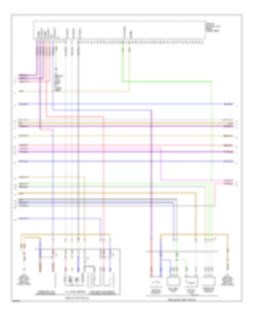
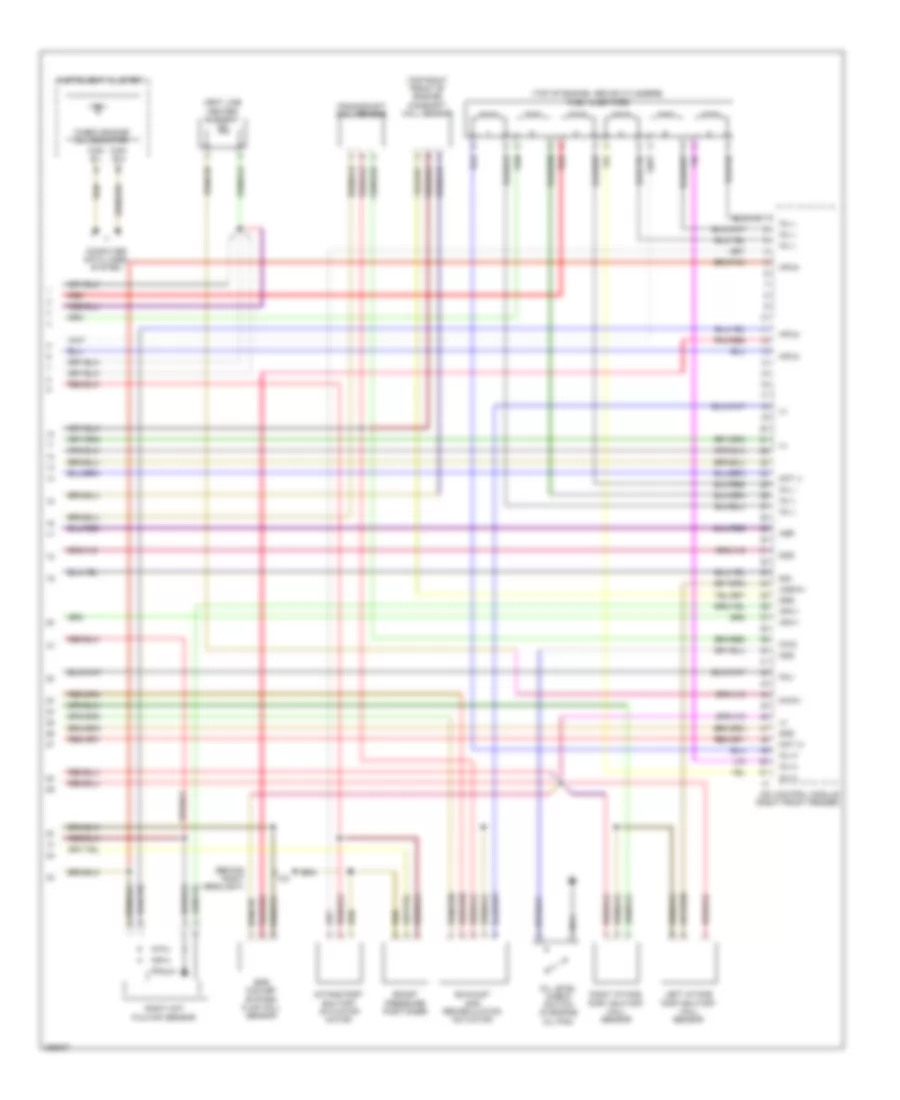
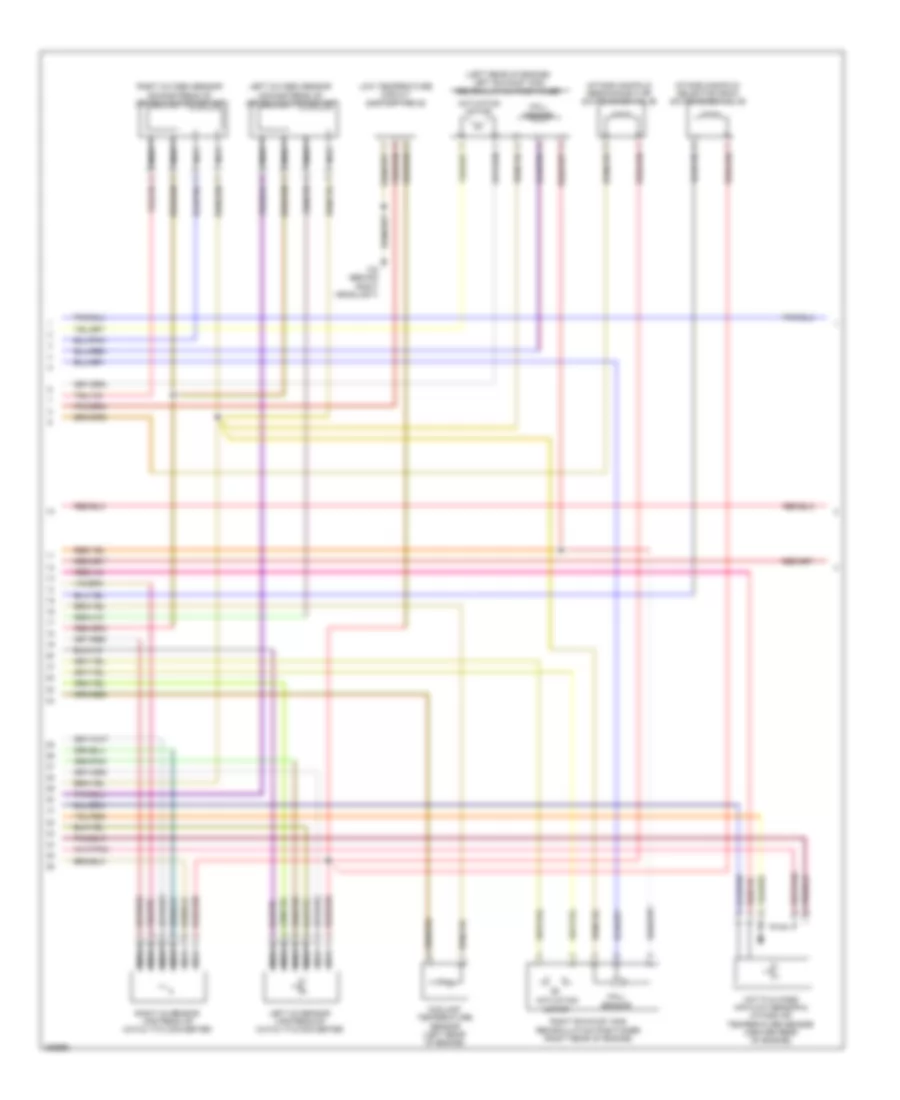
3.0L Turbo Diesel, Engine Performance Wiring Diagram (2 of 7) for Mercedes-Benz ML350 BlueTEC 2012
List of elements for 3.0L Turbo Diesel, Engine Performance Wiring Diagram (2 of 7) for Mercedes-Benz ML350 BlueTEC 2012:
- (left rear engine mount) left switchable engine mount
- (right rear engine mount) right switchable engine mount
- Can-i h
- Can-i l
- E1a
- Fuse 150a
- Fuse 15a
- Fuse 20a
- Fuse 5a
- Fuse 7.5a
- Gr pras
- Hot at all times
- Hot w/ circuit 15 relay energized
- Ia pras
- Ia trats
- Interior prefuse box
- Is t15
- Lines system computer data
- Os rarv
- Ot rapmp
- Ov rh1
- Pnk
- Ramvh1
- Ramvl1
- Rear fuse block
- Red
- Scrm1
- W7 (behind trim, right rear of cargo area)
3.0L Turbo Diesel, Engine Performance Wiring Diagram (3 of 7) for Mercedes-Benz ML350 BlueTEC 2012
List of elements for 3.0L Turbo Diesel, Engine Performance Wiring Diagram (3 of 7) for Mercedes-Benz ML350 BlueTEC 2012:
- (-)
- 15a
- Bf rals1
- Bf rals2
- Bf rals3
- Delivery pump
- Empty
- Fill level sensor
- Full
- Heating element
- Os raht1
- Os raht2
- Os raht3
- Pressure line heating element
- Pressure sensor
- Red
- Reserve
- Scrm(-)
- Scrm3
- Switch over
- Tank heating element & temperature sensor
- Valve
- Vv 5vpras
- W7 (behind trim, right rear of cargo area)
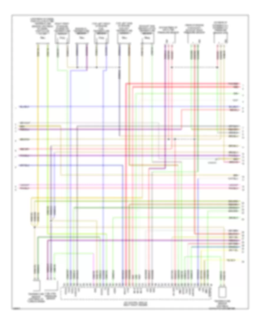
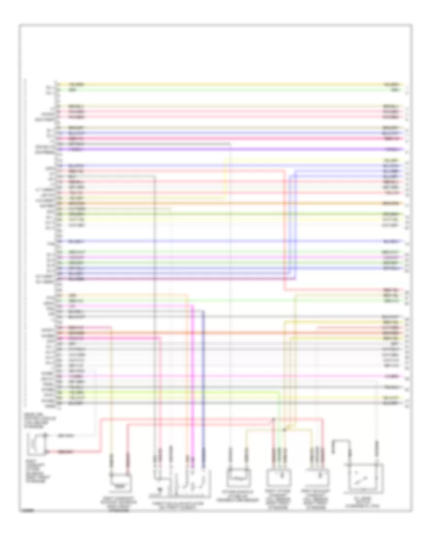
3.0L Turbo Diesel, Engine Performance Wiring Diagram (4 of 7) for Mercedes-Benz ML350 BlueTEC 2012
List of elements for 3.0L Turbo Diesel, Engine Performance Wiring Diagram (4 of 7) for Mercedes-Benz ML350 BlueTEC 2012:
- ( rear of engine, in exhaust) exhaust back pressure sensor
- (-)
- (on rear of
- (right front of engine) charge air temperature sensor
- (top left front of engine) fuel temperature sensor
- (top left side of engine) coolant temperature sensor
- (upstream of diesel particulate filter) temperature sensor upstream of diesel particular filter
- +5v
- A-eka-r
- Cdi control module (right front fender)
- Cvh
- Differential) differential pressure sensor (dpf)
- Downstream of air filter pressure sensor
- Drs
- Ea lds
- Eka-a
- Engine oil temperature sensor
- Exhaust gas recirculation temperature sensor
- Exts1
- Exts2
- Fuel-high pressure sensor
- Iats3
- Inj h
- Kts-s
- Ldr
- Ls1
- Ls1hk
- Lsh1hk
- Lshk
- Pnk/red
- Rds
- Red
- Sig
- T2-s
- Tag1
- Temperature sensor upstream catalytic converter
- Temperature sensor upstream of turbocharger
- Tmot
- Toel
- X18/3-c1
- Zme+
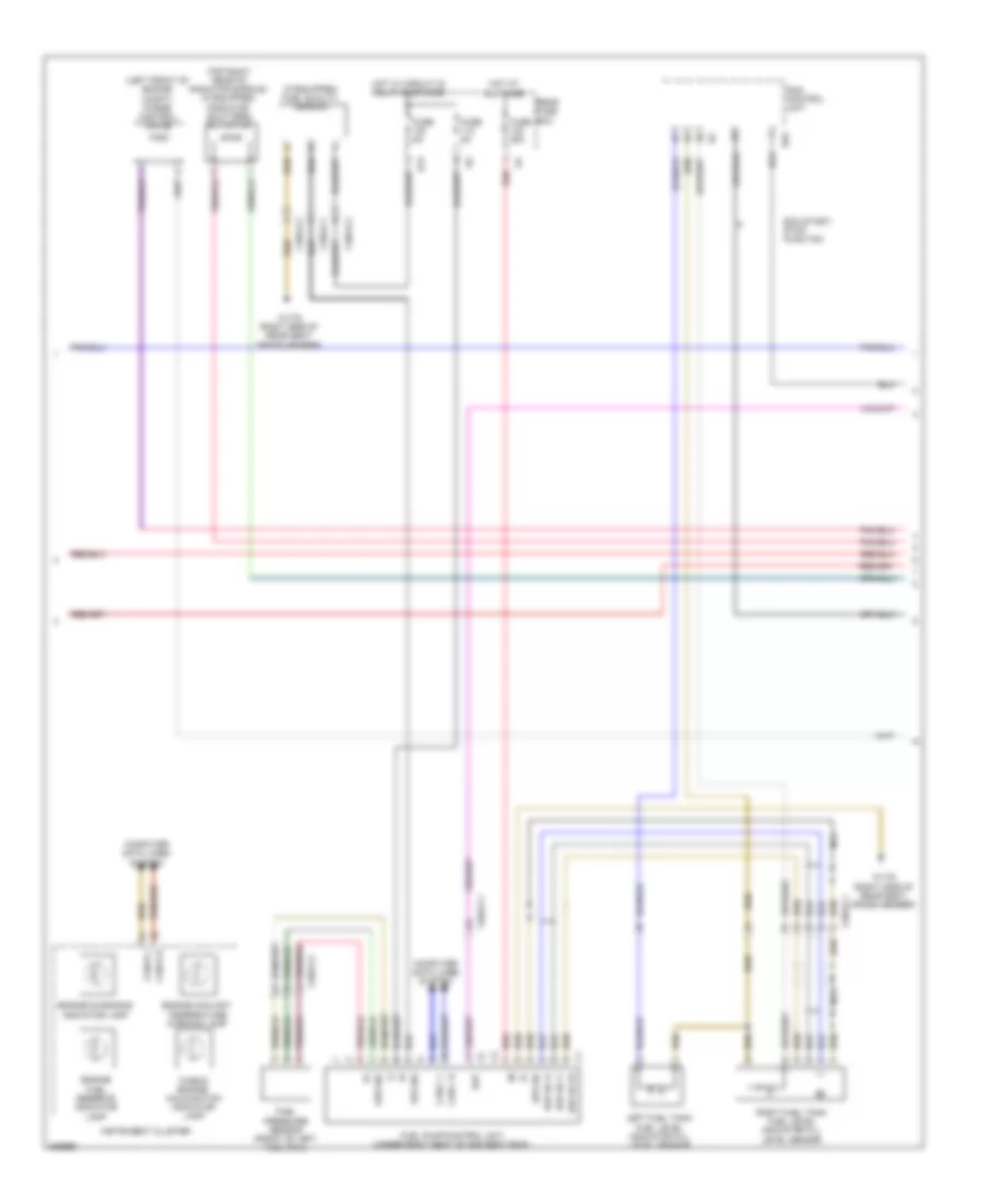
3.0L Turbo Diesel, Engine Performance Wiring Diagram (5 of 7) for Mercedes-Benz ML350 BlueTEC 2012
List of elements for 3.0L Turbo Diesel, Engine Performance Wiring Diagram (5 of 7) for Mercedes-Benz ML350 BlueTEC 2012:
- (+)
- (-)
- Can-c h
- Can-c l
- Computer data lines system
- Coolant pump switchover valve
- Ds sig
- Ds+
- Ds-
- Ekp-lauf
- Fuel pressure sensor (front of left fuel rail)
- Fuel pump control module
- Fuse 25a
- Fuse 5a
- Hot at all times
- Hot w/ circuit 15 relay energized
- Left fuel tank fuel level indicator fill level sensor
- Nca
- Oxygen sensor upstream of catalytic converter
- Pnk/red
- Pressure regulator valve (left front of engine)
- Quantity control valve
- Rear fuse box
- Red
- W17/6 (right side of rear seat cross member)
- X18/3-c1
- X25/2-c1
- X26/31-c1
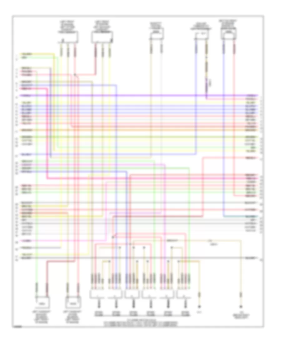
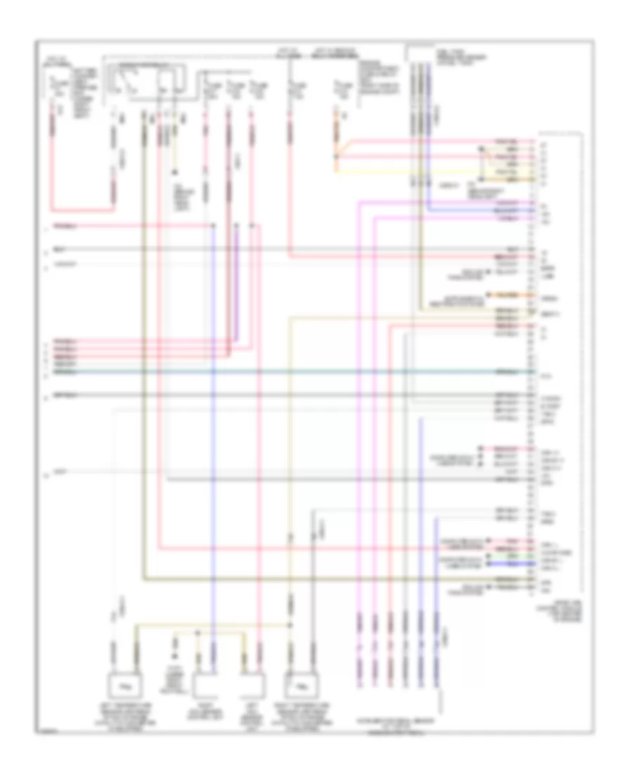
3.0L Turbo Diesel, Engine Performance Wiring Diagram (6 of 7) for Mercedes-Benz ML350 BlueTEC 2012
List of elements for 3.0L Turbo Diesel, Engine Performance Wiring Diagram (6 of 7) for Mercedes-Benz ML350 BlueTEC 2012:
- (right front of engine)
- 1.zyl
- 2.zyl
- 3.zyl
- 4.zyl
- 5.zyl
- 6.zyl
- Boost pressure sensor
- Consation sensor for fuel filter w/ heating element
- Cylinder glow plug 1
- Cylinder glow plug 2
- Cylinder glow plug 3
- Cylinder glow plug 4
- Cylinder glow plug 5
- Cylinder glow plug 6
- Egr (agr) cooler bypass flap switchover valve
- Fuel pump (fp) & right fuel tank fuel level indicator fill level sensor
- Glow time output stage (top front c1 of engine)
- Kfh21
- Kfhzz
- Left hot film maf sensor
- Lin
- Nca
- Red
- Starting/ charging system
- Throttle valve actuator (on throttle body)
- W11
- W12 (under center console)
- Wss
- X18/3-c1
- X26/31-c1
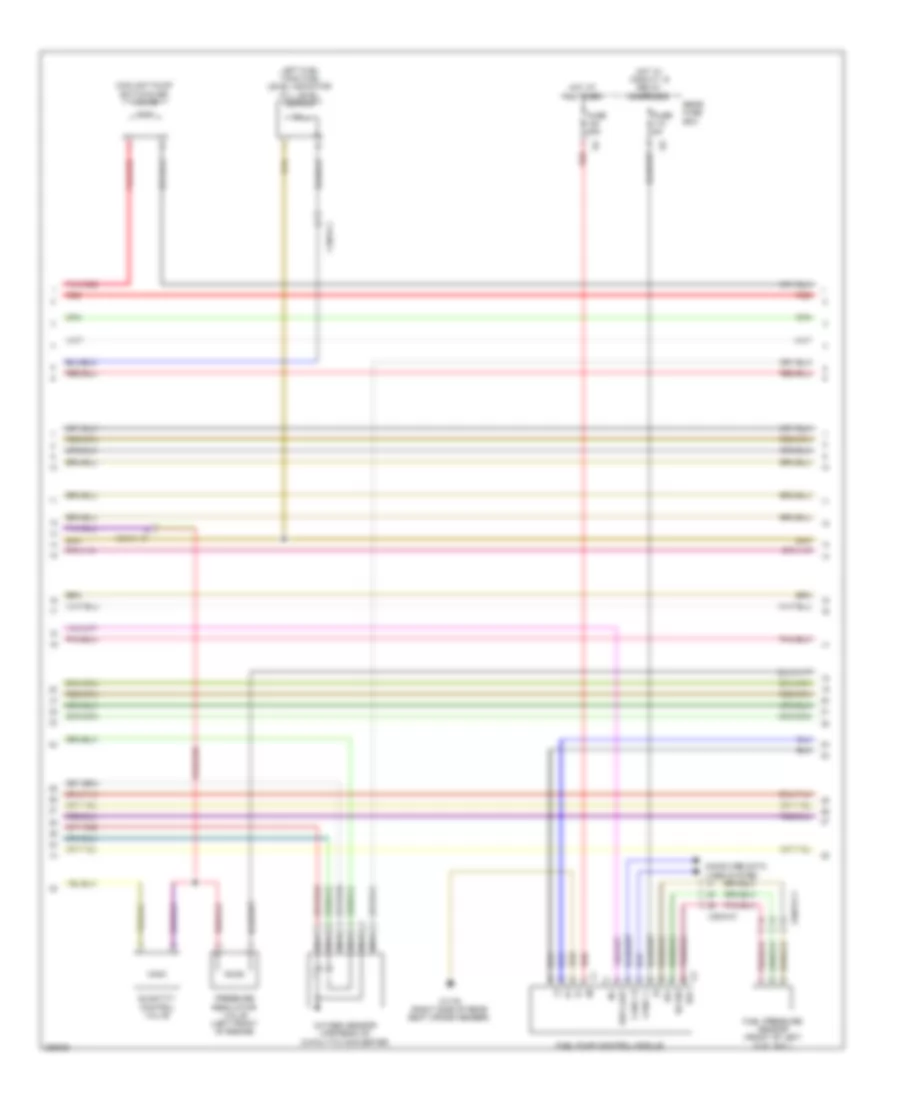
3.0L Turbo Diesel, Engine Performance Wiring Diagram (7 of 7) for Mercedes-Benz ML350 BlueTEC 2012
List of elements for 3.0L Turbo Diesel, Engine Performance Wiring Diagram (7 of 7) for Mercedes-Benz ML350 BlueTEC 2012:
- "check engine" mil indicator
- (+)
- (behind right headlight)
- (top of engine, above cylinders) fuel injectors
- (top right front of engine) camshaft hall sensor
- A-eka-i
- Agr
- Boost pressure positioner
- Can- b h
- Can- b l
- Cdi control module (right front fender)
- Computer data lines system
- Crankshaft hall sensor
- Dds
- Drs
- Egr cooler bypass flap hall sensor
- Exhaust gas recirculation actuator
- Gnd
- Hfm-0
- Hfm-1
- Hfm-2
- Inj h
- Inj l
- Instrument cluster
- Intake port shutoff actuator motor
- Kwg
- Left intake port shutoff hall sensor
- Mot (+)
- Mot (-)
- Nca
- Ods
- Oil level check switch (in engine oil pan)
- Pcv
- Pnk/red
- Red
- Right hot film maf sensor
- Right intake port shutoff hall sensor
- S-chv
- Sig
- Vent line heater element
3.5L
3.5L, Engine Performance Wiring Diagram (1 of 6) for Mercedes-Benz ML350 BlueTEC 2012
List of elements for 3.5L, Engine Performance Wiring Diagram (1 of 6) for Mercedes-Benz ML350 BlueTEC 2012:
- (+)
- (-)
- +5v
- A s agr2p
- A t agr2m
- Dcm
- Dcp
- E f agrp1
- E f agrp2
- Fsoel
- Imp
- Inj h
- Inj l
- Intake manifold intake air temperature sensor
- Ip1s
- Ip2s
- Ks2b
- Ls2hk
- Lsh1hk
- Lshk
- Lshvk1
- Me-sfi (me) control module (top center of engine)
- Nca
- Nwae2
- Nwg1
- Nwge2
- Nwsa1
- Nwsa2
- Nwse1
- Nwse2
- Oil level switch (in engine oil pan)
- Right camshaft exhaust solenoid (right front of engine)
- Right camshaft intake solenoid (right front of engine)
- Right exhaust camshaft hall sensor (right front of engine)
- Right intake camshaft hall sensor (right front of engine)
- Sig
- Sig ntemp
- Sig res
- Sig-aslts
- Sig-press
- Throttle valve actuator (on throttle body)
- Ths
- Zu 1
- Zu 2
- Zu 3
- Zu 4
- Zu 5
- Zu 6
3.5L, Engine Performance Wiring Diagram (2 of 6) for Mercedes-Benz ML350 BlueTEC 2012
List of elements for 3.5L, Engine Performance Wiring Diagram (2 of 6) for Mercedes-Benz ML350 BlueTEC 2012:
- (bottom front of engine) engine oil pump valve
- (left front of engine) left exhaust camshaft hall sensor
- (left front of engine) left intake camshaft hall sensor
- Coolant thermostat heating element
- Cylinder ignition coils (cylinder ignition coils 1, 2 & 3: top of right cylinder bank) (cylinder ignition coils 4, 5 & 6: top of left cylinder bank)
- Left camshaft exhaust solenoid (left front of engine)
- Left camshaft intake solenoid (left front of engine)
- Nca
- Quantity control valve
- Sig
- Spark plugs
- W11
- W2 (behind right headlight)
- X26-c1
3.5L, Engine Performance Wiring Diagram (3 of 6) for Mercedes-Benz ML350 BlueTEC 2012
List of elements for 3.5L, Engine Performance Wiring Diagram (3 of 6) for Mercedes-Benz ML350 BlueTEC 2012:
- (+)
- (-)
- (cylinder ports) fuel injector cylinders
- (in fuel tank) fuel tank pressure & temperature sensor
- A t agr1m
- A t agr1p
- Crankshaft hall sensor
- Ef hfm1
- Inj h
- Inj l
- Knock sensor 1
- Knock sensor 2
- Ks1a
- Ks1b
- Ks2a
- Kwga
- Lin c1
- Lsh2hk
- Lshvk2
- Lsu1a
- Lsu1p
- Lsu1un
- Lsu1vm
- Lsu2ia
- Lsu2ip
- Lsu2un
- Lsu2vm
- Me-sfi (me) control module (top center of engine)
- Nwga1
- Pnk
- Pressure sensor downstream of throttle valve
- Ref1
- Sig
- Sig pmot
- Sig sw
- Sig-temp
- Starting/charging system
- Tmot1
- X26-c4
3.5L, Engine Performance Wiring Diagram (4 of 6) for Mercedes-Benz ML350 BlueTEC 2012
List of elements for 3.5L, Engine Performance Wiring Diagram (4 of 6) for Mercedes-Benz ML350 BlueTEC 2012:
- (left rear of engine) left exhaust gas recirculation positioner
- Actuation motor
- Coolant temperature sensor (left rear of engine)
- Hall sensor
- Hot film mass air flow sensor & intake air temperature sensor (center rear of engine)
- Intake manifold resonance flap switchover valve
- Intake manifold selector drum switchover valve
- Left o2 sensor upstream of catalytic converter
- Left oxygen sensor downstream of catalytic converter
- Low temperature circuit shutoff valve
- Nca
- Right exhaust gas recirculation positioner (right rear of engine)
- Right o2 sensor upstream of catalytic converter
- Right oxygen sensor downstream of catalytic converter
- W2 (behind right headlight)
3.5L, Engine Performance Wiring Diagram (5 of 6) for Mercedes-Benz ML350 BlueTEC 2012
List of elements for 3.5L, Engine Performance Wiring Diagram (5 of 6) for Mercedes-Benz ML350 BlueTEC 2012:
- "check engine" malfunction indicator lamp
- (+)
- (-)
- (if equipped) fuel quality sensor
- (left front of engine compt) purge control valve
- (top right rear of radiator shroud) (if equipped) radiator shutters actuator
- Can c h
- Can c l
- Can-b h
- Can-b l
- Computer data lines system
- Eco start/ stop function
- Ekp
- Ekp-ec-u
- Ekp-ec-v
- Ekp-ec-w
- Ekp-sh
- Engine coolant temperature warning lamp
- Engine diagnosis indicator lamp
- Engine fuel reserve indicator lamp
- Fqs sig
- Fuel pressure sensor (front of left fuel rail)
- Fuel pump control unit (under right seat of 2nd seat row)
- Fuse 25a
- Fuse 5a
- Hot at all times
- Hot w/ circuit 15 relay energized
- Instrument cluster
- Kds sig
- Left fuel tank fuel level indicator fill level sensor
- Nca
- Rear fuse box
- Red
- Right fuel tank fuel level indicator fill level sensor
- S13
- Sam control unit
- Uh2
- W17/6 (right side of rear seat cross member)
- X18/3-c1
- X18/3-c2
- X25/2-c1
3.5L, Engine Performance Wiring Diagram (6 of 6) for Mercedes-Benz ML350 BlueTEC 2012
List of elements for 3.5L, Engine Performance Wiring Diagram (6 of 6) for Mercedes-Benz ML350 BlueTEC 2012:
- (behind right headlight)
- +5v
- 15v
- A s hr (hss)
- A s sam
- Aav
- Accelerator pedal sensor (at top of accelerator pedal)
- Battery compart- ment prefuse box (under right front seat)
- Can c h
- Can c l
- Can e1 h
- Can e1 l
- Can i h
- Can i l
- Circuit 87m relay
- Computer data lines system
- Cooling fans system
- Crash
- E a dst
- Ekpr
- Engine compartment fuse & relay box (right side of engine compt)
- Fuel tank pressure sensor (in fuel tank)
- Fuse 15a
- Fuse 20a
- Fuse 40a
- Fuse 7.5a
- Hot at all times
- Hot w/ backup relay energized
- Kla
- Left nox sensor control unit
- Left temperature sensor upstream of nox storage catalytic converter (if equipped)
- Lpv
- Lues
- Me-sfi (me) control module (top center of engine)
- Mr1
- Mr2
- Pnk
- Right nox sensor control unit
- Right temperature sensor upstream of nox storage catalytic converter (if equipped)
- S13
- Sewf 3
- Sp1s
- Sp2s
- Str
- Str+
- Tag 2
- W15/1 (under right front footwell)
- W2 (behind right head- light)
- X18/3-c2
- X25/2-c1
- X25/2-c2
- X26-c1