ENGINE PERFORMANCE
2.5L TURBO
2.5L Turbo, Engine Performance Wiring Diagram (1 of 5) for Subaru Forester X Premium 2012

List of elements for 2.5L Turbo, Engine Performance Wiring Diagram (1 of 5) for Subaru Forester X Premium 2012:
- (passenger side fuse & relay block) a/f oxygen sensor relay
- (passenger side fuse & relay block) main relay
- Accelerator pedal position sensor (under left side of dash)
- Air conditioning system
- Anti-theft system
- B135
- B136
- B145
- B36
- B97
- Computer data lines system
- Cooling fans system
- Cruise control system
- Electronic throttle control relay (passenger side fuse & relay block)
- Engine control module (under right side of dash)
- Fuse 15a
- Fuse sbf-5 30a
- Fuse sbf-7 30a
- Hot at all times
- J/c b83 (right side of dash)
- Main fuse box (m/b) (left side of engine compt)
- Mass air flow & intake air temperature sensor (air intake tube)
- Pnk
- Red
- Right fuse & relay block
- Shield
- Starting/charging system
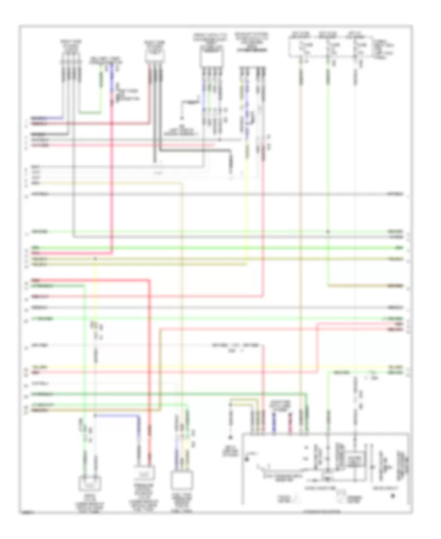
2.5L Turbo, Engine Performance Wiring Diagram (2 of 5) for Subaru Forester X Premium 2012
List of elements for 2.5L Turbo, Engine Performance Wiring Diagram (2 of 5) for Subaru Forester X Premium 2012:
- (exhaust system, after catalytic converter) rear oxygen sensor
- (front catalytic converter inlet) front oxygen (a/f) sensor
- (right side of dash) j/c b122
- (right side of dash) j/c b138
- B36
- B36 i1
- B52
- B75
- B76
- B97
- B99 r3
- Can transceiver & receiver
- Combination meter
- Computer data lines system
- Delivery (test) mode connector
- Drain valve (under rear of vehicle, near fuel tank)
- Drive circuit
- E2 b21
- Engine coolant
- Fuel tank pressure sensor (top of fuel tank)
- Fuse & relay box (f/b) (left kick panel)
- Fuse 10a
- Fuse 15a
- Gb-10 (center of dash)
- Ge (left side of engine assembly)
- Hot at all times
- Hot in on or start
- I/f
- I102
- Light ind temp warning engine coolant
- Malfunction ind light
- Micro computer
- Nca
- Oil pressure
- Pnk
- Pressure control solenoid valve (under rear of vehicle, near fuel tank)
- R15
- R167
- R168
- R57
- Red
- Shield
- Speedo- meter
- T5 b19
- Tacho- meter
- Temp ind
- Test mode b364 sub b363 connector
- Warning ind
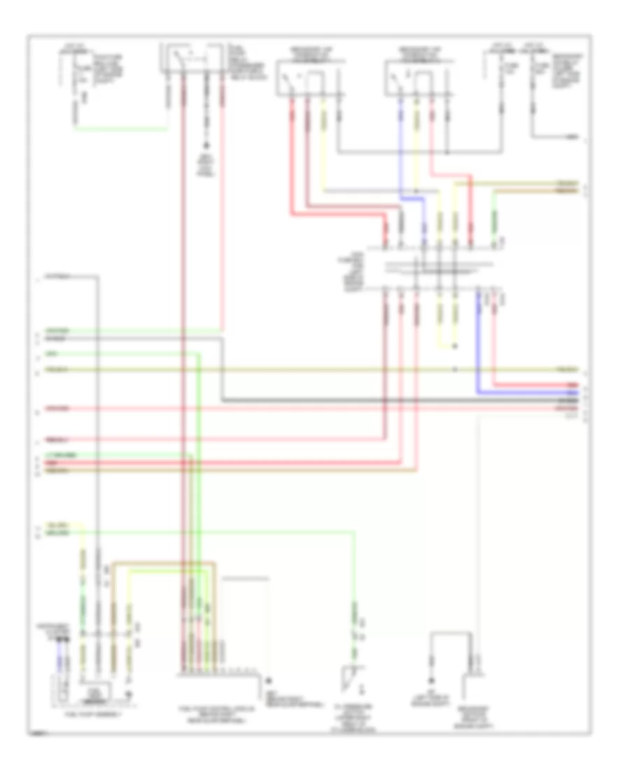
2.5L Turbo, Engine Performance Wiring Diagram (3 of 5) for Subaru Forester X Premium 2012
List of elements for 2.5L Turbo, Engine Performance Wiring Diagram (3 of 5) for Subaru Forester X Premium 2012:
- B143
- B144
- B186
- B21
- B97
- F37
- Fuel pump assembly
- Fuel pump control module (behind right rear quarterpanel)
- Fuel pump relay (passenger side fuse & relay block)
- Fuel temp sensor
- Fuse 10a
- Fuse 15a
- Fuse 60a
- Gb-3 (right kick panel)
- Gb-7 (behind right rear quarterpanel)
- Gp (left side of engine compt)
- Hot at all times
- Instrument cluster system
- Main fuse box (m/b) (left side of engine compt)
- Nca
- Oil pressure switch (upper right front of cylinder block)
- R15
- R57
- Red
- Secondary air combination valve relay 1
- Secondary air combination valve relay 2
- Secondary air pump (front of engine compt)
- Secondary air relay holder (left side of engine compt)
- Shield
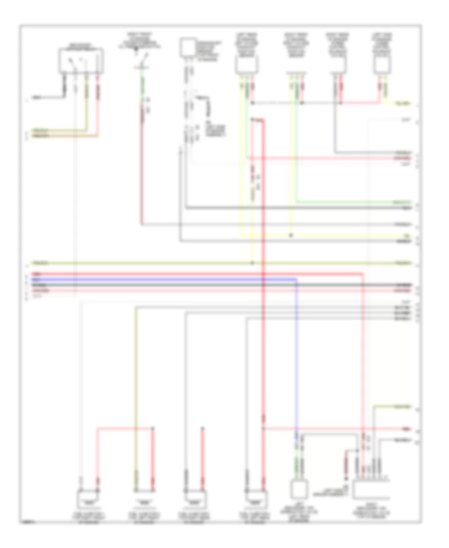
2.5L Turbo, Engine Performance Wiring Diagram (4 of 5) for Subaru Forester X Premium 2012
List of elements for 2.5L Turbo, Engine Performance Wiring Diagram (4 of 5) for Subaru Forester X Premium 2012:
- (left rear of engine) left intake camshaft position sensor
- (left side of engine) purge control solenoid valve 1
- (right front of engine) power steering oil pressure switch
- (right rear of engine) purge control solenoid valve 2
- (right rear of engine) right intake camshaft position sensor
- B21
- B21 e2
- Crankshaft position sensor (top front of engine)
- E2 b21
- Fuel injector 1 (top right front of engine)
- Fuel injector 2 (top left front of engine)
- Fuel injector 3 (top right rear of engine)
- Fuel injector 4 (top left rear of engine)
- Ge (left side of engine assembly)
- Left secondary air combination valve (left rear of engine)
- Nca
- Red
- Right secondary air combination valve (top of engine)
- Secondary air pump relay
- Shield
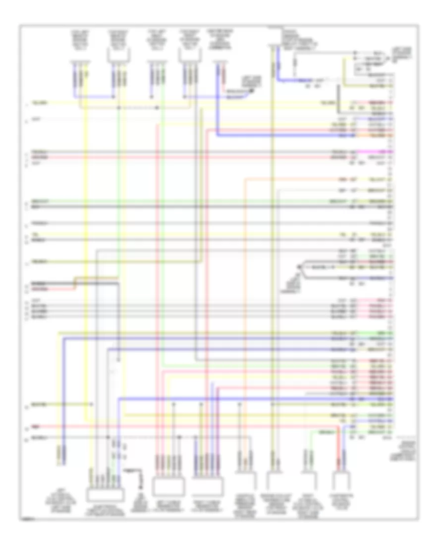
2.5L Turbo, Engine Performance Wiring Diagram (5 of 5) for Subaru Forester X Premium 2012
List of elements for 2.5L Turbo, Engine Performance Wiring Diagram (5 of 5) for Subaru Forester X Premium 2012:
- (center rear of engine) leak diagnosis connector
- (left side of engine assembly) ge
- (top left front of engine) ignition coil 2
- (top left rear of engine) ignition coil 4
- (top right front of engine) ignition coil 1
- (top right rear of engine) ignition coil 3
- B134
- B137
- B21
- E2 b21
- Electronic throttle control (top rear of engine)
- Engine control module (under right side of dash)
- Engine coolant temperature sensor (top front of engine)
- Ge (left side of engine assembly)
- Knock sensor (top of engine, below throttle body assembly)
- Left intake oil flow control solenoid valve (left side of engine)
- Left tumble generator valve assembly
- Manifold absolute pressure sensor (right rear of engine)
- Pnk
- Red
- Right intake oil flow control solenoid valve (right side of engine)
- Right tumble generator valve assembly
- Shield
- Wastegate control solenoid valve