ENGINE PERFORMANCE
2.5L
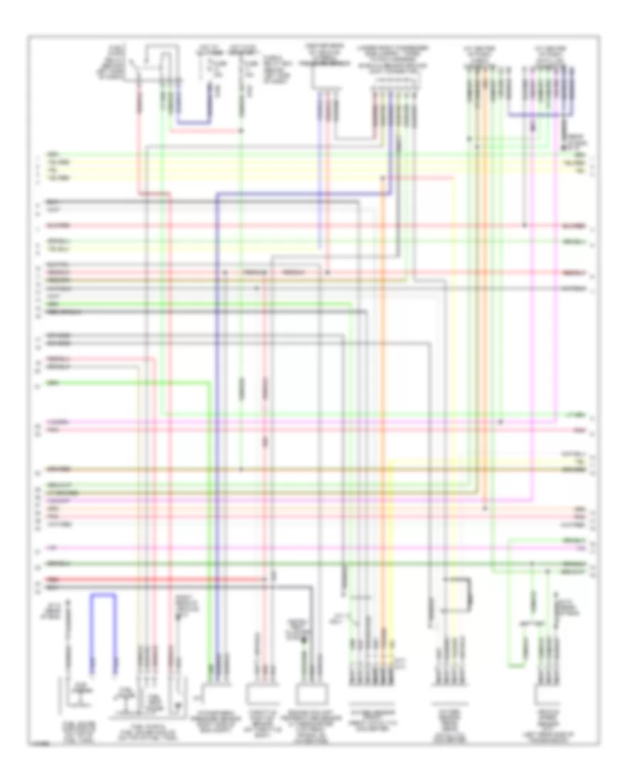
2.5L, Engine Performance Wiring Diagrams (1 of 3) for Subaru Outback 2000

List of elements for 2.5L, Engine Performance Wiring Diagrams (1 of 3) for Subaru Outback 2000:
- (a/t)
- (behind left side of dash) interrupt relay
- (behind right side of dash) main relay
- (m/t)
- (on air cleaner case) intake air temperature sensor
- (on throttle body) intake manifold pressure sensor
- (pins 15 22 & 23 not used)
- A/t
- Acc
- Air condi- tioning system
- Air conditioning system
- B135
- B136
- Braided
- Camshaft position sensor (on left camshaft support)
- Crankshaft position sensor (front of eng, on oil pump)
- Defogger system
- Engine control module (behind right side of dash)
- Exterior light system
- Exterior lights sysyem
- G115 (rear of eng)
- G121 (center of firewall)
- Hot at all times
- Ignition switch
- Inhibitor switch (right side of transmission)
- Knock sensor (top rear of eng)
- M/t
- Nca
- Neutral position switch (on transfer case)
- Off
- Pnk
- Power steering oil pressure switch (on power steering oil pump)
- Pressure sensor & intake air temperature sensor (top of front eng)
- Red
- Shield & sensor ground joint connector (under front passenger side carpet, taped to pcm harness)
- Start
- Starter interlock relay (behind left side of dash)
- Starting system
- Starting/ charging system
- W/ security
- W/o security
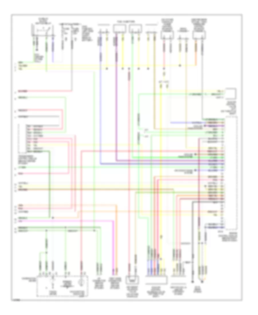
2.5L, Engine Performance Wiring Diagrams (2 of 3) for Subaru Outback 2000
List of elements for 2.5L, Engine Performance Wiring Diagrams (2 of 3) for Subaru Outback 2000:
- (a/t)
- (at center of dash) check connector
- (at center of dash) data link connector
- (center rear of vehicle) internal pressure sensor
- (m/t)
- (rear of eng) g115
- (right rear of vehicle) g410
- (under front passenger side carpet, taped to pcm harness) shield & sensor ground joint connector
- A/t
- A/t only
- Atmospheric pressure sensor (right side of eng compt)
- B152
- B158
- Braided
- Catalytic converter)
- Engine coolant temperature sensor & thermometer (top front or eng, on water pipe)
- Fuel gauge
- Fuel gauge sub module (on top of fuel tank)
- Fuel pump & fuel gauge module (on top of fuel tank)
- Fuel pump relay (behind left side of dash)
- Fuel temp gauge
- Fuse & relay box (behind left side of dash)
- Fuse 15a
- G115 (rear of eng)
- Hot at all times
- Hot in on or start
- Instru- ment cluster system
- M/t
- Nca
- Oxygen sensor (front) (front catalytic converter)
- Oxygen sensor (rear) (rear
- Pnk
- Red
- Sub gauge
- Throttle position sensor (on throttle body)
- Vehicle speed sensor (m/t) (left rear side of transmission)
2.5L, Engine Performance Wiring Diagrams (3 of 3) for Subaru Outback 2000
List of elements for 2.5L, Engine Performance Wiring Diagrams (3 of 3) for Subaru Outback 2000:
- (center rear of fuel tank) pressure control solenoid valve
- (in relay block) ignition relay
- (m/t)
- (on intake manifold) purge control solenoid valve
- A/t
- A13
- A21
- Air assist solenoid valve (on intake manifold)
- Air conditioning system
- B13
- B134
- B20
- Braided
- Combination meter
- Cooling fans system
- Drain valve
- Engine control module (behind right side of dash)
- F37
- F68
- Fuel injectors
- Fuse 15a
- Fuse sbf-5 30a
- G115 (rear of eng)
- G121 (center of fire- wall)
- Hot at all times
- I10
- I11
- I12
- Idle air control solenoid valve (on throttle body)
- Idle air control valve (m/t) (on throttle body)
- Ignition coil & ignitor (top front of eng)
- M/t
- Main fuse box (left side of eng compt, rear of battery)
- Malfunction indicator lamp
- Op connector (behind center of dash)
- Pnk
- Red
- Speedo- meter circuit
- Tacho- meter
- Test mode connector (behind center of dash)
- Transmission control module (behind center of dash)