ENGINE PERFORMANCE
2.0L TURBO DIESEL
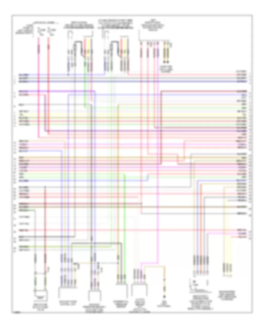
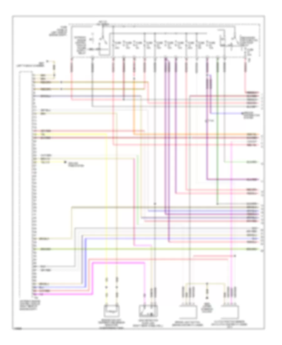
2.0L Turbo Diesel, Engine Performance Wiring Diagram (1 of 6) for Volkswagen Golf 2013

List of elements for 2.0L Turbo Diesel, Engine Performance Wiring Diagram (1 of 6) for Volkswagen Golf 2013:
- (accelerator pedal assembly) accelerator pedal position sensor 1 & 2
- (left kick panel) g602
- (left plenum chamber) g607
- (on air intake tube) mass air flow (maf) sensor
- Auxiliary heater heating element (left side of hvac housing)
- Cooling fans system
- Cylinder head)
- Engine control module (right rear engine compt)
- Engine coolant temperature sensor (on radiator) (right rear of
- Exhaust gas temperature (egt) sensor 1 (on turbocharger)
- Exhaust gas temperature (egt) sensor 2 (egr housing)
- Exhaust gas temperature (egt) sensor 3 (egr housing)
- Exhaust gas temperature (egt) sensor 4 (egr housing outlet)
- Fuse 10a
- Fuse 20a
- Fuse 30a
- Fuse 50a
- Fuse 5a
- Fuse panel b (left side of engine compt)
- Heater/ heat output switch (w/ auxiliary heater & w/o a/c system)
- Hot at all times
- Red
- Steering column electronics control module (top of steering column)
- T14a
- T16r
- T20c
- T40
- T94
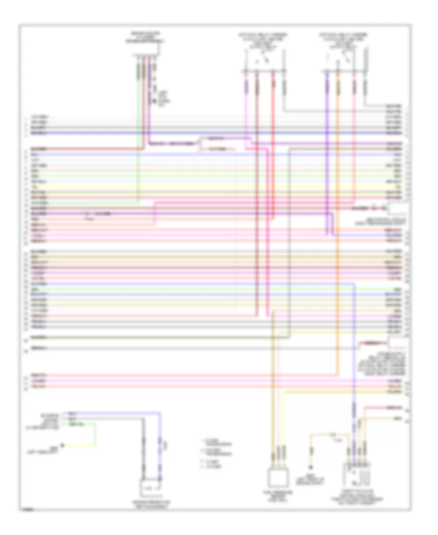
2.0L Turbo Diesel, Engine Performance Wiring Diagram (2 of 6) for Volkswagen Golf 2013
List of elements for 2.0L Turbo Diesel, Engine Performance Wiring Diagram (2 of 6) for Volkswagen Golf 2013:
- (egr housing)
- (left side of dash) vehicle electrical system control module
- Clutch position sensor (m/t) (on clutch master cylinder)
- Computer data lines system
- Differential pressure sensor
- Egr cooler switch over valve
- Egr potenti- ometer & egr vacuum regulator solenoid valve (on egr vacuum regulator assembly)
- Engine speed (rpm) sensor (left rear side of engine)
- Exhaust door control unit
- Exhaust pressure sensor 1 (auxiliary fuel pump bracket)
- Fuse 40a
- Fuse 80a
- Fuse panel a (left side of engine compt)
- G44 (left kick panel)
- Heated oxygen sensor & oxygen sensor heater
- Hot at all times
- Nca
- Oxygen sensor after three way catalytic converter & oxygen sensor 1 after catalytic converter heater
- Red
- T14a
- T52b
- T52c
- T5ab
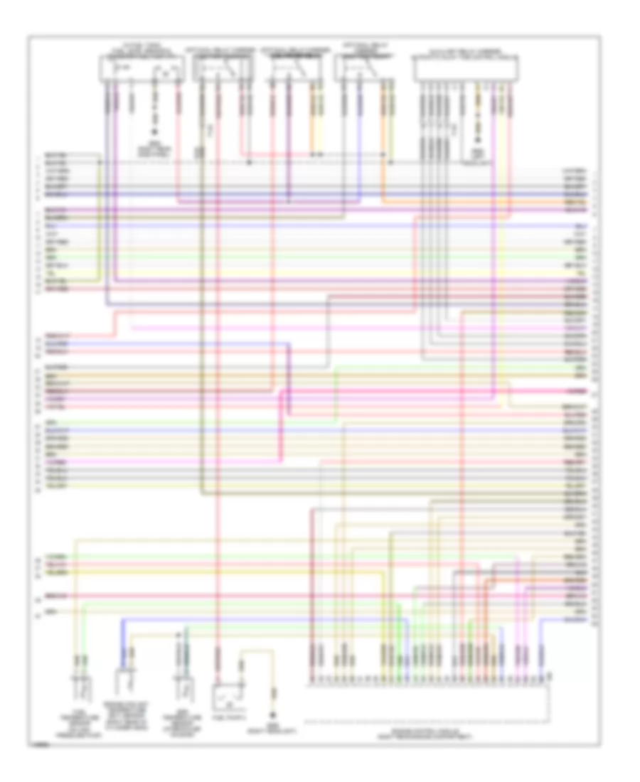
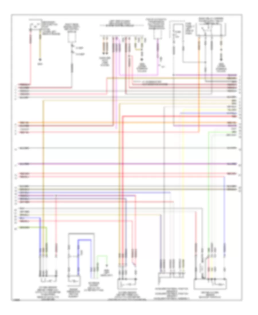
2.0L Turbo Diesel, Engine Performance Wiring Diagram (3 of 6) for Volkswagen Golf 2013
List of elements for 2.0L Turbo Diesel, Engine Performance Wiring Diagram (3 of 6) for Volkswagen Golf 2013:
- (brake master cylinder) brake light switch
- (left kick panel) g44
- (optional relay carrier) (w/auxiliary heater) high heat output relay
- (optional relay carrier) (w/auxiliary heater) low heat output relay
- Abs control module (right rear engine compt)
- Engine preheating heating element
- Exterior socket 230v/110v (w/ retrofitting)
- Fuel pressure sensor (fuel rail)
- G642 (left front of engine compt)
- G655 (left headlight)
- Red
- T14a
- T2ap
- Throttle valve control module & throttle position sensor (on throttle body)
- Transmission
- W/ dsg
- W/ esp
- W/o dsg
- W/o esp
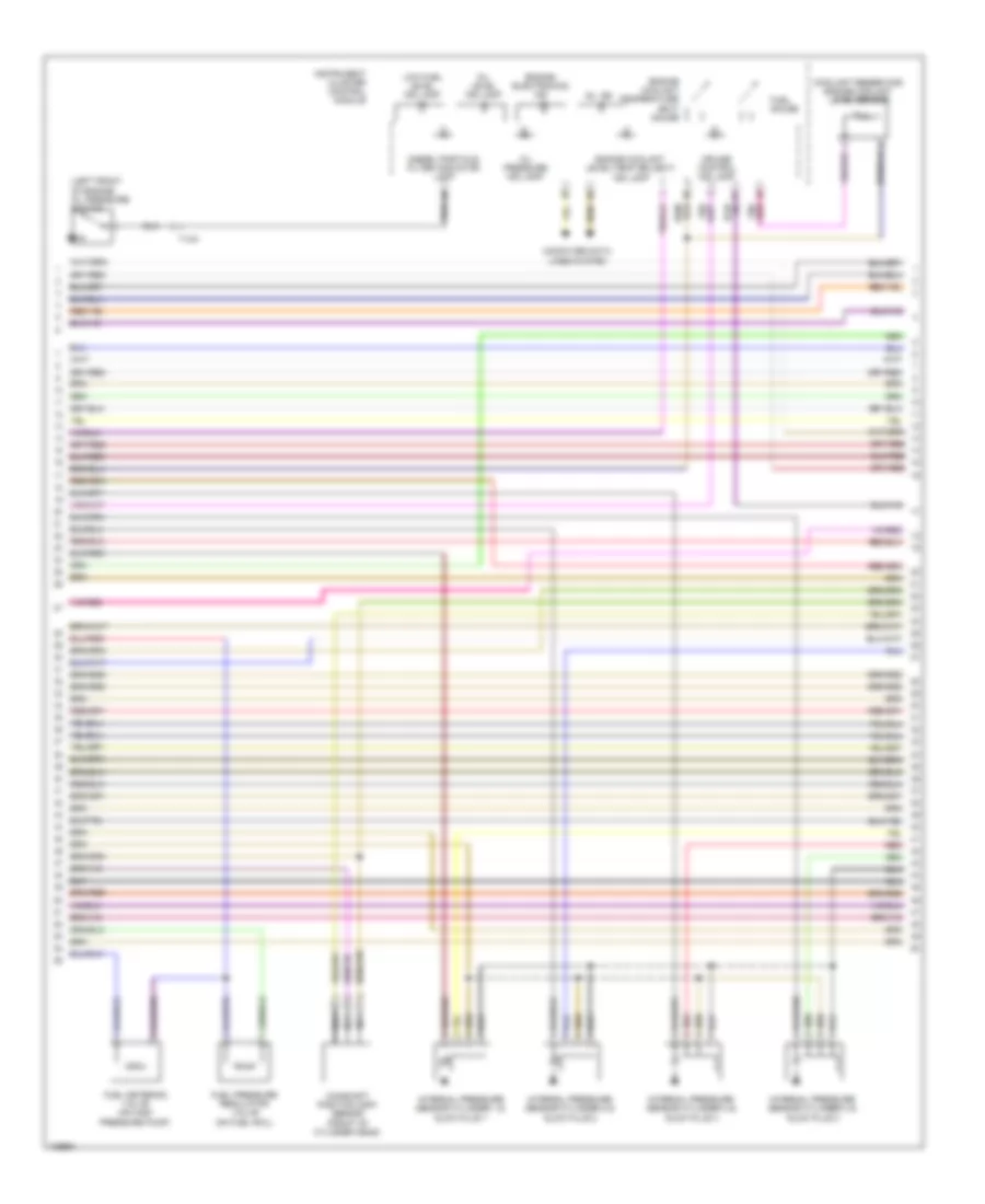
2.0L Turbo Diesel, Engine Performance Wiring Diagram (4 of 6) for Volkswagen Golf 2013
List of elements for 2.0L Turbo Diesel, Engine Performance Wiring Diagram (4 of 6) for Volkswagen Golf 2013:
- (auxiliary relay carrier) automatic glow time control module
- (in fuel tank) fuel level sensor & transfer fuel pump (fp)
- (optional relay carrier) fuel primer relay
- (optional relay carrier) fuel pump relay
- (optional relay carrier) fuel pump relay 2
- Egr temperature sensor (intercooler housing)
- Engine control module (right rear engine compartment)
- Engine coolant temperature (ect) sensor (right rear of cylinder head)
- Fuel pump 2
- Fuel temperature sensor (on high pressure pump)
- G655 (left headlight)
- G656 (right headlight)
- G682 (right rear side panel)
- T14a
- T60
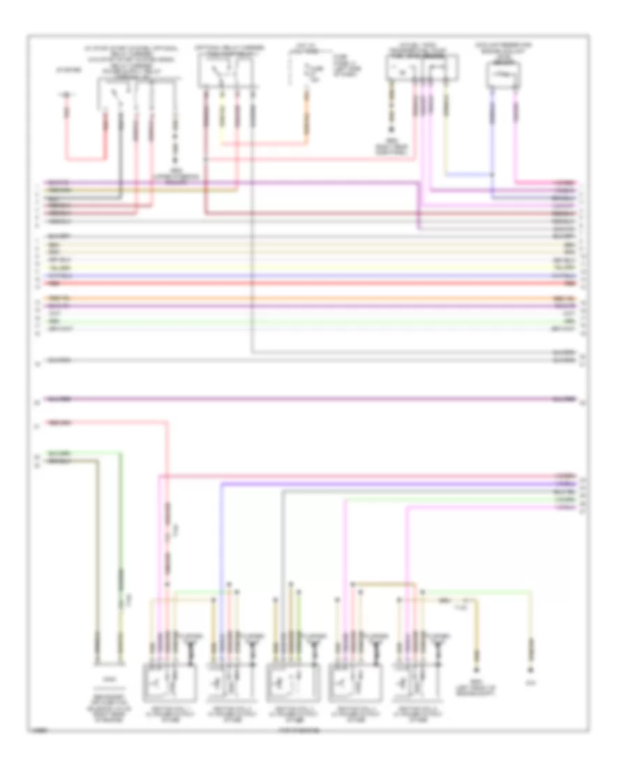
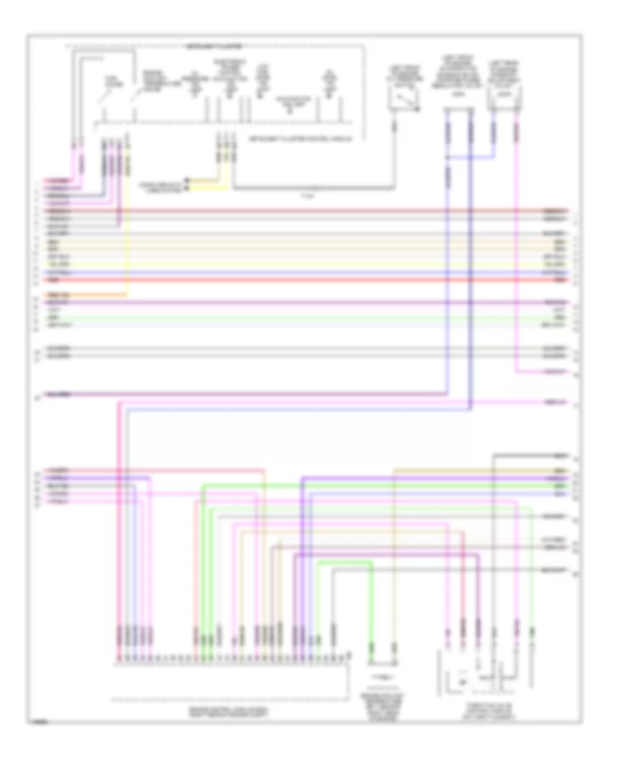
2.0L Turbo Diesel, Engine Performance Wiring Diagram (5 of 6) for Volkswagen Golf 2013
List of elements for 2.0L Turbo Diesel, Engine Performance Wiring Diagram (5 of 6) for Volkswagen Golf 2013:
- (coolant reservoir) engine coolant level sensor
- (left front of engine) oil pressure switch
- Camshaft position (cmp) sensor (front of cylinder head)
- Computer data lines system
- Cruise control ind lamp
- Diesel particle filter indicator lamp
- Engine coolant level/temp (ecl/ect) ind lamp
- Engine coolant temperature (ect) gauge
- Engine electronics ind
- Fuel gauge
- Fuel metering valve (on high pressure pump)
- Fuel pressure regulator valve (on fuel rail)
- Instrument cluster control module
- Internal pressure sensor cylinder 1 & glow plug 1
- Internal pressure sensor cylinder 2 & glow plug 2
- Internal pressure sensor cylinder 3 & glow plug 3
- Internal pressure sensor cylinder 4 & glow plug 4
- Low fuel level ind lamp
- Mil ind
- Nca
- Oil level ind lamp
- Oil pressure ind lamp
- Red
- T14a
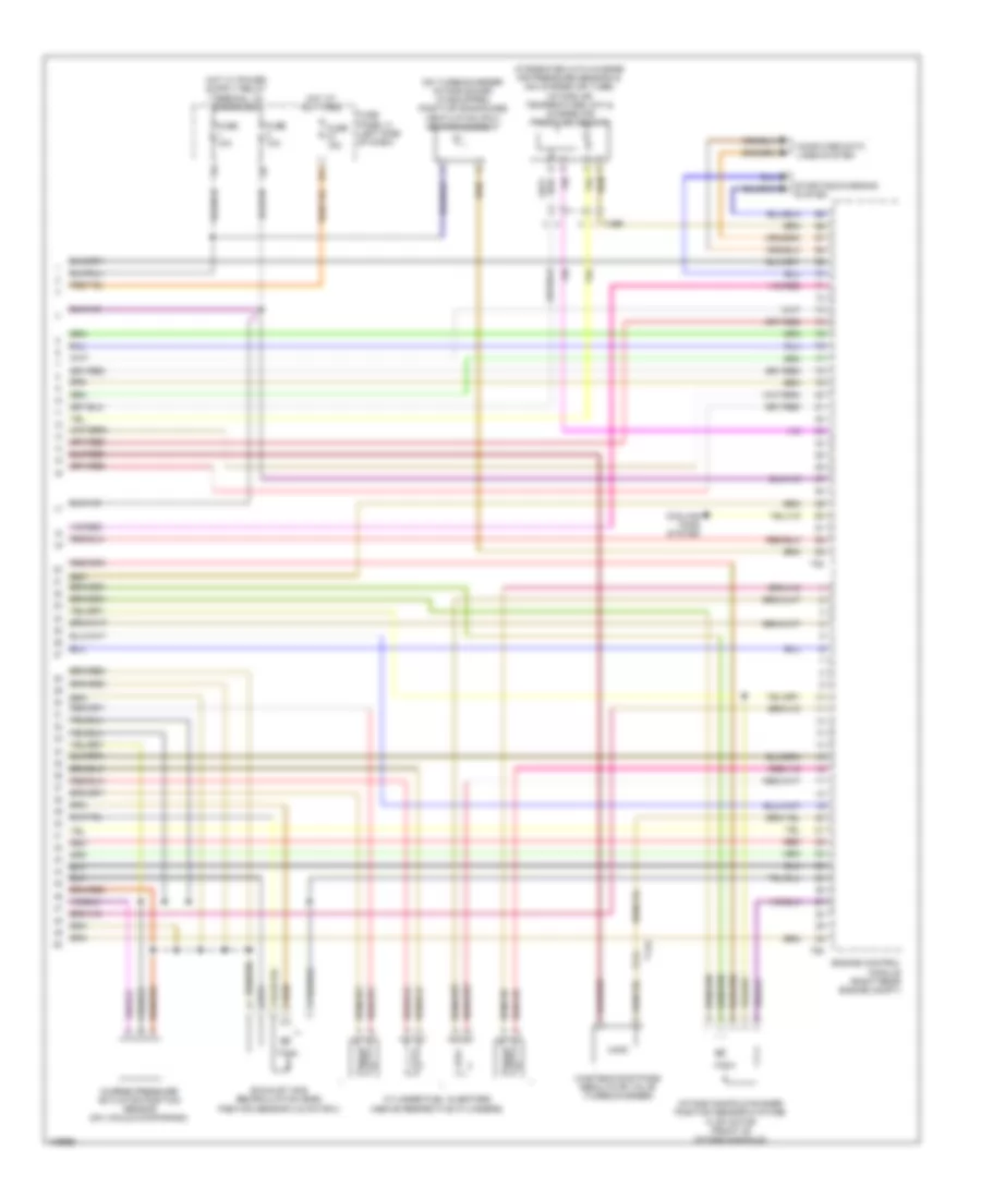
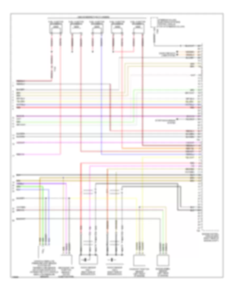
2.0L Turbo Diesel, Engine Performance Wiring Diagram (6 of 6) for Volkswagen Golf 2013
List of elements for 2.0L Turbo Diesel, Engine Performance Wiring Diagram (6 of 6) for Volkswagen Golf 2013:
- (ntegrated with charge air pressure sensor) & (on charge air tube) intake air temperature (iat) & charge air pressure sensor
- (on turbocharger intake scoop) (if equipped) positive crankcase ventilation (pcv) heating element
- 27a
- Charge pressure actuator position sensor (on vacuum diaphragm)
- Computer data lines system
- Cooling fans system
- Cylinder fuel injectors (above respective cylinders)
- Engine control module (right rear engine compt)
- Exhaust gas recirculation (egr) position sensor 2 & motor 2
- Fuse 10a
- Fuse 15a
- Fuse panel c (left side of dash)
- Hot at all times
- Intake manifold runner position sensor & intake flap motor (front of intake manifold)
- Red
- Starting/charging system
- T14a
- T4bf
- T60
- T94
- Wastegate bypass regulator valve (turbocharger)
2.5L
2.5L, Engine Performance Wiring Diagram (1 of 5) for Volkswagen Golf 2013
List of elements for 2.5L, Engine Performance Wiring Diagram (1 of 5) for Volkswagen Golf 2013:
- Brake light switch (brake master cylinder)
- Clutch position sensor (on clutch master cylinder) (m/t)
- Cooling fans system
- Engine coolant temperature sensor (radiator) (in expansion tank)
- Fuse 10a
- Fuse 15a
- Fuse 20a
- Fuse 40a
- Fuse 5a
- Fuse panel b (left side of engine compt)
- G605 (upper steering column)
- G607 (left plenum chamber)
- Ground distribution system
- Hot at all times
- Leak detection pump (ldp) (right rear wheelwell)
- Motronic engine control module (right rear of engine compt)
- Secondary air injection (air) pump relay
- T14a
- T40
- T94
2.5L, Engine Performance Wiring Diagram (2 of 5) for Volkswagen Golf 2013
List of elements for 2.5L, Engine Performance Wiring Diagram (2 of 5) for Volkswagen Golf 2013:
- (left side of dash) vehicle electrical system control module
- (right rear engine compt) abs control module
- (top of automatic transmission) multifunction transmission range switch
- A/t
- Accelerator pedal position sensor & accelerator pedal position sensor 2 (accelerator pedal assembly)
- Computer data lines system
- Engine preheating heating element
- Exterior socket 230v & 110v (w/ retrofitting)
- Fuse 10a
- Fuse panel c (left side of dash)
- G605 (upper steering column)
- G640
- G655 (left headlight)
- Heated oxygen sensor (exhaust manifold)
- Nca
- Oxygen sensor behind three way catalytic converter (if equipped) (rear of catalytic converter)
- Oxygen sensor center three way catalytic converter (center of catalytic converter)
- Red
- Secondary air injection pump motor (lower left rear of engine)
- T10q
- T2ap
- T52b
- T52c
- W/ access/start authorization system
- W/ esp
- W/o esp
2.5L, Engine Performance Wiring Diagram (3 of 5) for Volkswagen Golf 2013
List of elements for 2.5L, Engine Performance Wiring Diagram (3 of 5) for Volkswagen Golf 2013:
- (coolant reservoir) engine coolant level sensor
- (in fuel tank) transfer fuel pump/ fuel level sensor
- (optional relay carrier) fuel pump relay
- (top of engine)
- 27a
- Fuse 15a
- Fuse panel c (left side of dash)
- G15
- G605 (upper steering column)
- G642 (left front of engine compt)
- G682 (right rear side panel)
- Hot at all times
- Ignition coil 1 w/ power output stage
- Ignition coil 2 w/ power output stage
- Ignition coil 3 w/ power output stage
- Ignition coil 4 w/ power output stage
- Ignition coil 5 w/ power output stage
- Nca
- Red
- Secondary air injection solenoid valve (right rear of engine)
- Starter
- T14a
- To spark plug
2.5L, Engine Performance Wiring Diagram (4 of 5) for Volkswagen Golf 2013
List of elements for 2.5L, Engine Performance Wiring Diagram (4 of 5) for Volkswagen Golf 2013:
- (left front of engine) evaporative emission (evap) canister purge regulator valve 1
- (left front of engine) oil pressure switch
- (left rear of engine) camshaft adjustment valve 1
- Computer data lines system
- Electronic power control malfunction ind lamp
- Engine control module (ecm) (right rear of engine compt)
- Engine coolant temperature (ect) sensor (right rear of engine)
- Engine coolant temperature gauge
- Fuel gauge
- Instrument cluster
- Instrument cluster control module
- Low fuel level ind lamp
- Malfunction ind lamp
- Oil level ind lamp
- Oil pressure ind lamp
- Red
- T14a
- T60
- Throttle valve control module (on throttle body)
2.5L, Engine Performance Wiring Diagram (5 of 5) for Volkswagen Golf 2013
List of elements for 2.5L, Engine Performance Wiring Diagram (5 of 5) for Volkswagen Golf 2013:
- (above respective cylinders)
- Camshaft position sensor (left front of engine)
- Computer data lines system
- Engine control module (ecm) (right rear of engine compt)
- Engine speed sensor (left rear of engine)
- Fuel injector cylinder 1
- Fuel injector cylinder 2
- Fuel injector cylinder 3
- Fuel injector cylinder 4
- Fuel injector cylinder 5
- Knock sensor (ks) 1 (right side of engine block)
- Knock sensor (ks) 2 (right side of engine block)
- Manifold absolute pressure (map) sensor & intake air temperature sensor (on intake manifold) & (integrated with manifold absolute pressure sensor)
- Nca
- Red
- Secondary air injection sensor 1 (on air injection pipe)
- Starting/charging system
- Steering column electronic systems control module (top of steering column)
- T14a
- T16r
- T60
- T94