ENGINE PERFORMANCE
2.5L TURBO
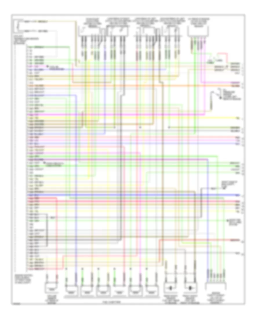
2.5L Turbo, Engine Performance Wiring Diagram (1 of 3) for Volvo S80 2004

List of elements for 2.5L Turbo, Engine Performance Wiring Diagram (1 of 3) for Volvo S80 2004:
- (at rear of engine) mass airflow (maf) sensor
- (in intake manifold) intake manifold pressure sensor
- (right front of eng compt) climate control system pressure sensor
- (right front of engine) oil level sensor
- 31/96 (right side of eng compt)
- A10
- A11
- A12
- A13
- A14
- A15
- A16
- A17
- A18
- A19
- A20
- A21
- A22
- A23
- A24
- A25
- A26
- A27
- A28
- A29
- A30
- A31
- A32
- A33
- A34
- A35
- A36
- A37
- A38
- A39
- A40
- A41
- A42
- A43
- A44
- A45
- A46
- A47
- A48
- A49
- A50
- A51
- A52
- A53
- A54
- A55
- A56
- A57
- A58
- A59
- A60
- A61
- A62
- A63
- A64
- A65
- A66
- A67
- A68
- A69
- A70
- Camshaft position sensor (top rear of engine)
- Camshaft sensor (if equipped)
- Computer data lines system
- Cooling fans system
- Engine control module (right side of engine compt, forward of strut tower)
- Engine throttle body
- Evap valve (left front of eng compt)
- Front knock sensor (top left front of eng)
- Fuel injectors
- Impulse sensor (rear of engine)
- Pnk
- Pressure & temperature sensor
- Rear knock sensor (top left rear of engine)
- Red
- Variable valve timing outlet solenoid (at top of engine)
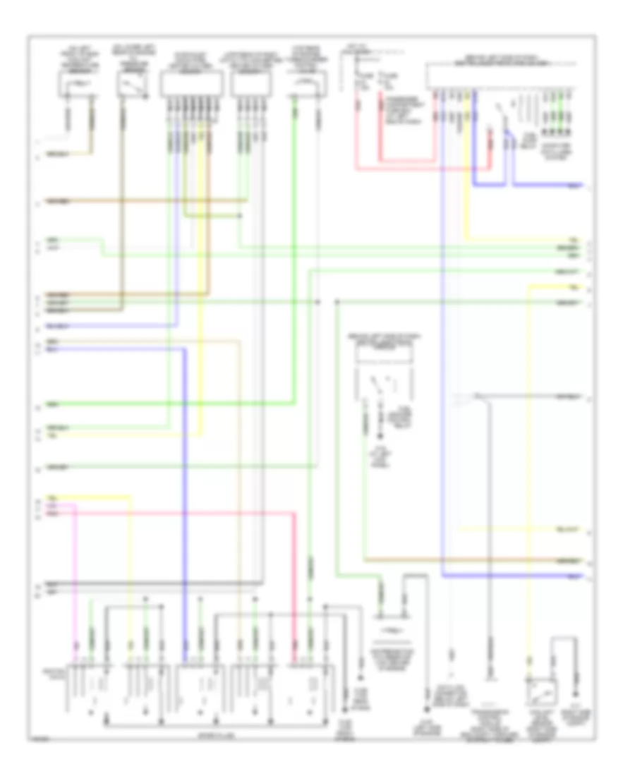
2.5L Turbo, Engine Performance Wiring Diagram (2 of 3) for Volvo S80 2004
List of elements for 2.5L Turbo, Engine Performance Wiring Diagram (2 of 3) for Volvo S80 2004:
- (behind left side of dash) central electronic module
- (behind left side of dash) central electronic module (cem)
- (in exhaust down pipe) heated oxygen sensor
- (on left front of eng) coolant temperature sensor
- (on lower left rear of engine) oil pressure sensor
- (top rear of engine) turbocharger control valve
- (upstream of right catalytic converter) heated oxygen sensor 1
- 31/1 (right side of engine compt)
- 31/6 (at left kick panel)
- 31/88 (top front of eng)
- 31/89 (top rear of eng)
- 31/91 (left side of engine)
- A20
- Air preheating ptc resistor (top center of engine)
- B14
- B17
- B18
- B22
- C14
- Computer data lines system
- Coolant level sensor (right side of engine compt)
- Data link connector (below left side of dash)
- Fuel leakage control relay
- Fuel pump relay
- Fuse 10a
- Fuse 15a
- Hot at all times
- Ignition coils
- Nca
- Passenger compartment fuse box (at left end of dash)
- Pnk
- Red
- Spark plugs
- Transmission control module (right side of eng compt, forward of strut tower)
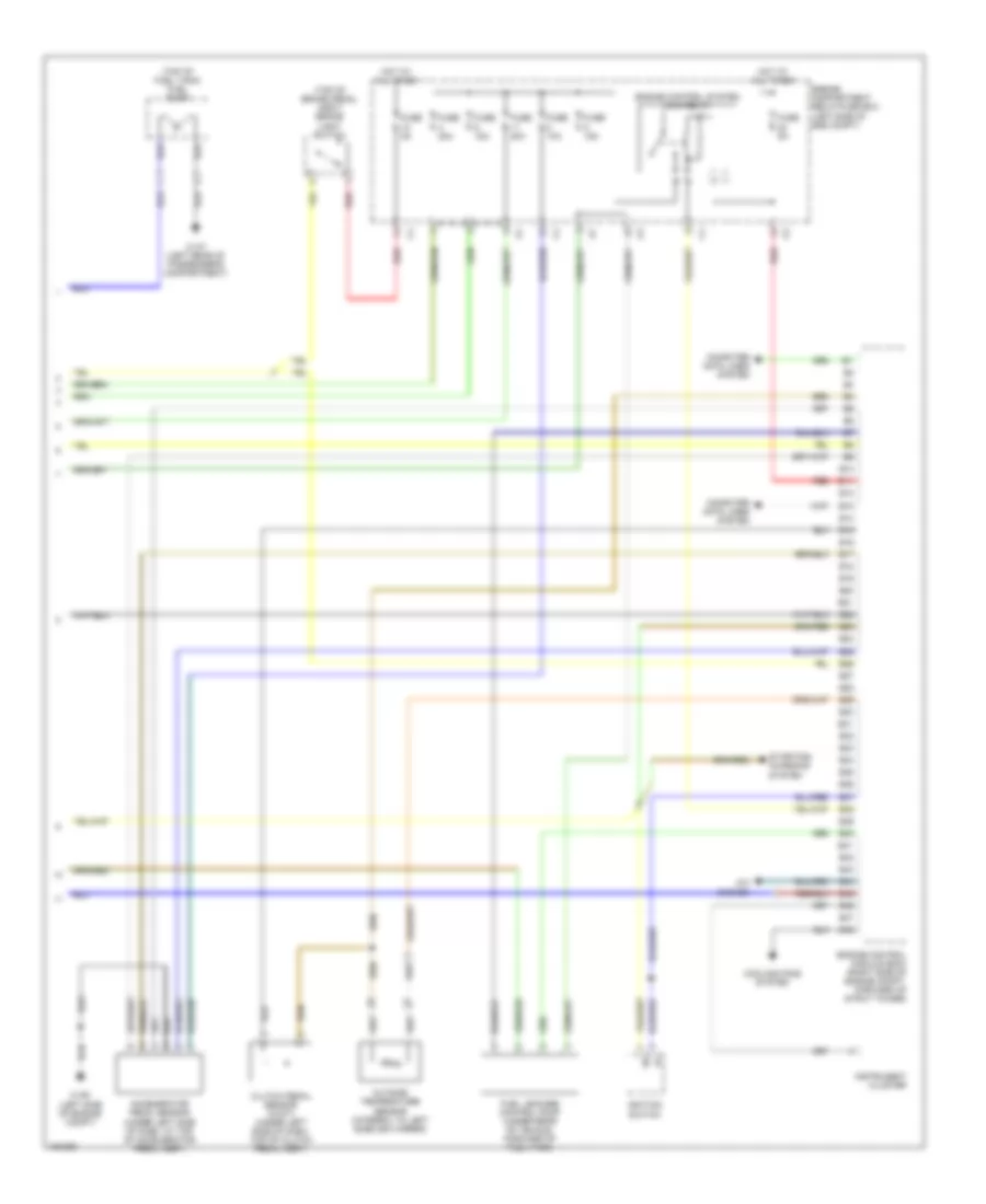
2.5L Turbo, Engine Performance Wiring Diagram (3 of 3) for Volvo S80 2004
List of elements for 2.5L Turbo, Engine Performance Wiring Diagram (3 of 3) for Volvo S80 2004:
- (top of brake pedal assy) brake light switch
- (top of fuel tank) fuel pump
- 31/47 (left rear of passenger's compartment)
- 31/93 (left side of engine compt)
- A/c system
- Accelerator pedal sensor (under left side of dash, at top of accelerator pedal assy)
- B10
- B11
- B12
- B13
- B14
- B15
- B16
- B17
- B18
- B19
- B20
- B21
- B22
- B23
- B24
- B25
- B26
- B27
- B28
- B29
- B30
- B31
- B32
- B33
- B34
- B35
- B36
- B37
- B38
- B39
- B40
- B41
- B42
- B43
- B44
- B45
- B46
- B47
- B48
- Clutch pedal sensor (w/m/t) (under left side of dash, top of clutch pedal assy)
- Computer data lines system
- Cooling fans system
- Engine compartment relay/fuse box (left side of eng compt)
- Engine control module (ecm) (right side of engine compt, forward of strut tower)
- Engine control system main relay
- Fuel leakage control pump (under rear of vehicle, forward of fuel tank)
- Fuse 10a
- Fuse 15a
- Fuse 20a
- Fuse 5a
- Hot at all times
- Ignition switch
- Instrument cluster
- Outside temperature sensor (integral to left sideview mirror)
- Red
- Starting/ charging system
2.9L
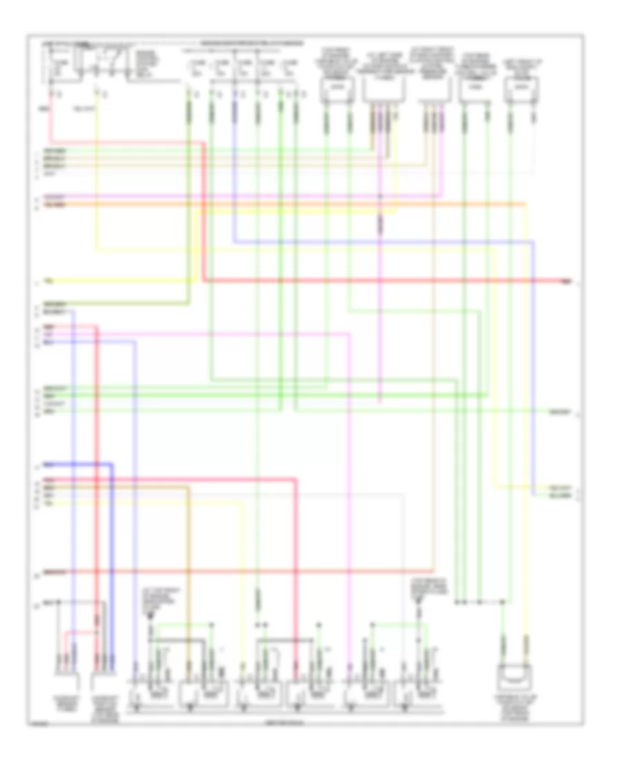
2.9L, Engine Performance Wiring Diagram (1 of 3) for Volvo S80 2004
List of elements for 2.9L, Engine Performance Wiring Diagram (1 of 3) for Volvo S80 2004:
- (at rear of engine on air intake) mass airflow sensor
- (downstream of left catalytic converter) heated oxygen sensor 4
- (in exhaust down pipe) heated oxygen sensor
- (right side of eng compt) 31/96
- (upstream of left catalytic converter) heated oxygen sensor 3
- (upstream of right catalytic converter) heated oxygen sensor (diagnosis 1)
- A10
- A11
- A12
- A13
- A14
- A15
- A16
- A17
- A18
- A19
- A20
- A21
- A22
- A23
- A24
- A25
- A26
- A27
- A28
- A29
- A30
- A31
- A32
- A33
- A34
- A35
- A36
- A37
- A38
- A39
- A40
- A41
- A42
- A43
- A44
- A45
- A46
- A47
- A48
- A49
- A50
- A51
- A52
- A53
- A54
- A55
- A56
- A57
- A58
- A59
- A60
- A61
- A62
- A63
- A64
- A65
- A66
- A67
- A68
- A69
- A70
- Computer data lines system
- Coolant temperature sensor (left front of engine)
- Cooling fans system
- Engine control module (ecm) (at right side of eng compt)
- Engine throttle body (on top of throttle body assembly)
- Front knock sensor (top left front of engine)
- Fuel injectors
- Impulse sensor (at rear of engine)
- Nca
- Oil pressure sensor (lower left rear of engine)
- Pnk
- Rear knock sensor (top left rear of engine)
- Red
- Turbo
- W/o turbo
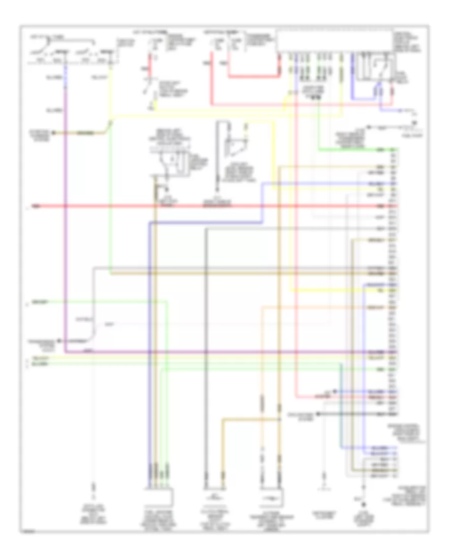
2.9L, Engine Performance Wiring Diagram (2 of 3) for Volvo S80 2004
List of elements for 2.9L, Engine Performance Wiring Diagram (2 of 3) for Volvo S80 2004:
- (at left side of engine) intake manifold temperature sensor (turbo)
- (at right front of eng compart) climate control system pressure sensor
- (at top front of engine, near spark plugs) 31/88
- (left front of eng compt) evap valve
- (top front of engine) variable valve timing outlet solenoid (turbo)
- (top rear of engine) turbocharger control valve (turbo)
- (top rear of engine, near spark plugs) 31/89
- Camshaft position sensor (top rear of engine)
- Camshaft sensor (turbo)
- Engine compartment relay/fuse box
- Engine control system main relay
- Fuse 10a
- Fuse 15a
- Fuse 20a
- Fuse 5a
- Hot at all times
- Ignition coils
- Pnk
- Red
- Variable valve timing outlet solenoid (top front of engine)
2.9L, Engine Performance Wiring Diagram (3 of 3) for Volvo S80 2004
List of elements for 2.9L, Engine Performance Wiring Diagram (3 of 3) for Volvo S80 2004:
- (behind left side of dash) central electronic module (cem)
- 31/1 (right side of engine compt)
- 31/48 (right rear of passenger's compartment, near floor)
- 31/6 (left kick panel)
- 31/93 (left side of engine compt)
- A/c system
- A20
- Acc
- Accelerator pedal (ap) position sensor (top of accelerator pedal assembly)
- B10
- B11
- B12
- B13
- B14
- B15
- B16
- B17
- B18
- B19
- B20
- B21
- B22
- B23
- B24
- B25
- B26
- B27
- B28
- B29
- B30
- B31
- B32
- B33
- B34
- B35
- B36
- B37
- B38
- B39
- B40
- B41
- B42
- B43
- B44
- B45
- B46
- B47
- B48
- C14
- Central electronic module (behind left side of dash)
- Clutch pedal sensor (w/m/t) (top of clutch pedal assy)
- Computer data lines system
- Coolant level sensor (right side of of eng compt, in coolant tank)
- Cooling fans system
- Data link connector (dlc) (below left side of dash)
- Engine compartment relay/fuse box
- Engine control module (ecm) (right side of eng compt)
- Fuel leakage control pump (under rear of vehicle, forward of fuel tank)
- Fuel leakage control relay
- Fuel pump
- Fuel pump relay
- Fuse 10a
- Fuse 15a
- Fuse 5a
- Hot at all times
- Ignition switch
- Instrument cluster
- Lock
- Nca
- Outside temperature sensor (integral to left sideview mirror)
- Passenger compartment fuse box
- Red
- Run
- Start
- Starting/ charging system
- Stoplight switch (top of brake pedal assy)
- Transmission system (w/a/t)
2.9L TURBO
2.9L Turbo, Engine Performance Wiring Diagram (1 of 3) for Volvo S80 2004
List of elements for 2.9L Turbo, Engine Performance Wiring Diagram (1 of 3) for Volvo S80 2004:
- (at rear of engine on air intake) mass airflow sensor
- (downstream of left catalytic converter) heated oxygen sensor 4
- (in exhaust down pipe) heated oxygen sensor
- (right side of eng compt) 31/96
- (upstream of left catalytic converter) heated oxygen sensor 3
- (upstream of right catalytic converter) heated oxygen sensor (diagnosis 1)
- A10
- A11
- A12
- A13
- A14
- A15
- A16
- A17
- A18
- A19
- A20
- A21
- A22
- A23
- A24
- A25
- A26
- A27
- A28
- A29
- A30
- A31
- A32
- A33
- A34
- A35
- A36
- A37
- A38
- A39
- A40
- A41
- A42
- A43
- A44
- A45
- A46
- A47
- A48
- A49
- A50
- A51
- A52
- A53
- A54
- A55
- A56
- A57
- A58
- A59
- A60
- A61
- A62
- A63
- A64
- A65
- A66
- A67
- A68
- A69
- A70
- Computer data lines system
- Coolant temperature sensor (left front of engine)
- Cooling fans system
- Engine control module (ecm) (at right side of eng compt)
- Engine throttle body (on top of throttle body assembly)
- Front knock sensor (top left front of engine)
- Fuel injectors
- Impulse sensor (at rear of engine)
- Nca
- Oil pressure sensor (lower left rear of engine)
- Pnk
- Rear knock sensor (top left rear of engine)
- Red
- Turbo
- W/o turbo
2.9L Turbo, Engine Performance Wiring Diagram (2 of 3) for Volvo S80 2004
List of elements for 2.9L Turbo, Engine Performance Wiring Diagram (2 of 3) for Volvo S80 2004:
- (at left side of engine) intake manifold temperature sensor (turbo)
- (at right front of eng compart) climate control system pressure sensor
- (at top front of engine, near spark plugs) 31/88
- (left front of eng compt) evap valve
- (top front of engine) variable valve timing outlet solenoid (turbo)
- (top rear of engine) turbocharger control valve (turbo)
- (top rear of engine, near spark plugs) 31/89
- Camshaft position sensor (top rear of engine)
- Camshaft sensor (turbo)
- Engine compartment relay/fuse box
- Engine control system main relay
- Fuse 10a
- Fuse 15a
- Fuse 20a
- Fuse 5a
- Hot at all times
- Ignition coils
- Pnk
- Red
- Variable valve timing outlet solenoid (top front of engine)
2.9L Turbo, Engine Performance Wiring Diagram (3 of 3) for Volvo S80 2004
List of elements for 2.9L Turbo, Engine Performance Wiring Diagram (3 of 3) for Volvo S80 2004:
- (behind left side of dash) central electronic module (cem)
- 31/1 (right side of engine compt)
- 31/48 (right rear of passenger's compartment, near floor)
- 31/6 (left kick panel)
- 31/93 (left side of engine compt)
- A/c system
- A20
- Acc
- Accelerator pedal (ap) position sensor (top of accelerator pedal assembly)
- B10
- B11
- B12
- B13
- B14
- B15
- B16
- B17
- B18
- B19
- B20
- B21
- B22
- B23
- B24
- B25
- B26
- B27
- B28
- B29
- B30
- B31
- B32
- B33
- B34
- B35
- B36
- B37
- B38
- B39
- B40
- B41
- B42
- B43
- B44
- B45
- B46
- B47
- B48
- C14
- Central electronic module (behind left side of dash)
- Clutch pedal sensor (w/m/t) (top of clutch pedal assy)
- Computer data lines system
- Coolant level sensor (right side of of eng compt, in coolant tank)
- Cooling fans system
- Data link connector (dlc) (below left side of dash)
- Engine compartment relay/fuse box
- Engine control module (ecm) (right side of eng compt)
- Fuel leakage control pump (under rear of vehicle, forward of fuel tank)
- Fuel leakage control relay
- Fuel pump
- Fuel pump relay
- Fuse 10a
- Fuse 15a
- Fuse 5a
- Hot at all times
- Ignition switch
- Instrument cluster
- Lock
- Nca
- Outside temperature sensor (integral to left sideview mirror)
- Passenger compartment fuse box
- Red
- Run
- Start
- Starting/ charging system
- Stoplight switch (top of brake pedal assy)
- Transmission system (w/a/t)