ENGINE PERFORMANCE
2.3L
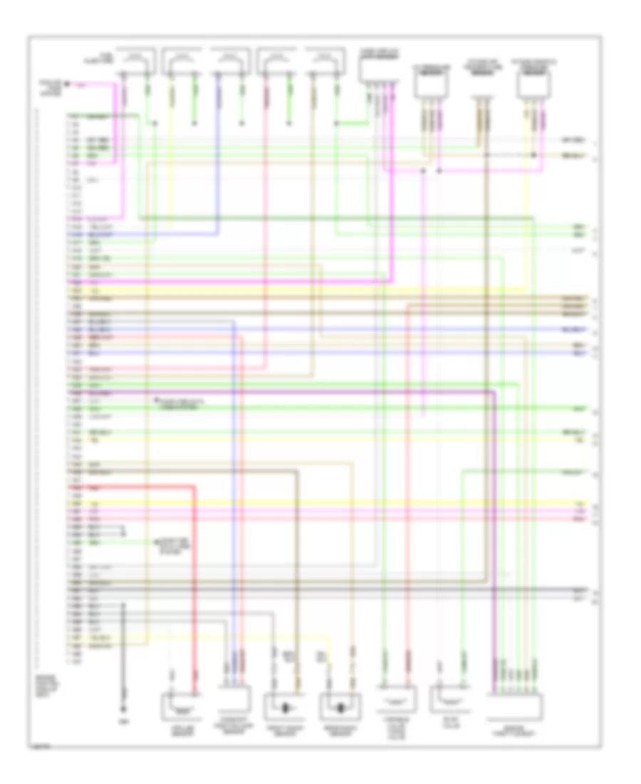
2.3L Turbo, Engine Performance Wiring Diagrams (1 of 3) for Volvo V70 T-5 2002

List of elements for 2.3L Turbo, Engine Performance Wiring Diagrams (1 of 3) for Volvo V70 T-5 2002:
- A/c pressure sensor
- A10
- A11
- A12
- A13
- A14
- A15
- A16
- A17
- A18
- A19
- A20
- A21
- A22
- A23
- A24
- A25
- A26
- A27
- A28
- A29
- A30
- A31
- A32
- A33
- A34
- A35
- A36
- A37
- A38
- A39
- A40
- A41
- A42
- A43
- A44
- A45
- A46
- A47
- A48
- A49
- A50
- A51
- A52
- A53
- A54
- A55
- A56
- A57
- A58
- A59
- A60
- A61
- A62
- A63
- A64
- A65
- A66
- A67
- A68
- A69
- A70
- Camshaft position (cmp) sensor
- Computer data lines system
- Cooling fans system
- Engine control module (ecm)
- Engine throttle body
- Evap valve
- Front knock sensor
- Fuel injectors
- G96
- Impulse sensor
- Intake air temperature sensor)
- Intake manifold pressure sensor
- Mass airflow (maf) sensor
- Pnk
- Rear knock sensor
- Red
- Variable valve timing valve
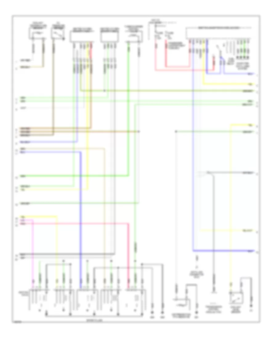
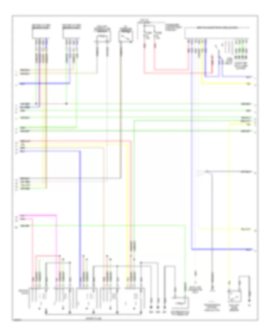
2.3L Turbo, Engine Performance Wiring Diagrams (2 of 3) for Volvo V70 T-5 2002
List of elements for 2.3L Turbo, Engine Performance Wiring Diagrams (2 of 3) for Volvo V70 T-5 2002:
- A20
- Air preheating ptc resistor
- B14
- B17
- B18
- B22
- C14
- Central electronic module (cem)
- Computer data lines system
- Coolant level sensor
- Coolant temperature sensor
- Data link connector (dlc)
- Fuel pump relay
- Fuse 10a
- Fuse 15a
- G88
- G89
- G91
- Heated oxygen sensor (ho2s) 1
- Heated oxygen sensor (ho2s) 2
- Hot at all times
- Ignition coils
- Oil pressure sensor
- Passenger compartment fuse box
- Pnk
- Red
- Spark plugs
- Transmission control module (tcm)
- Turbocharger control valve
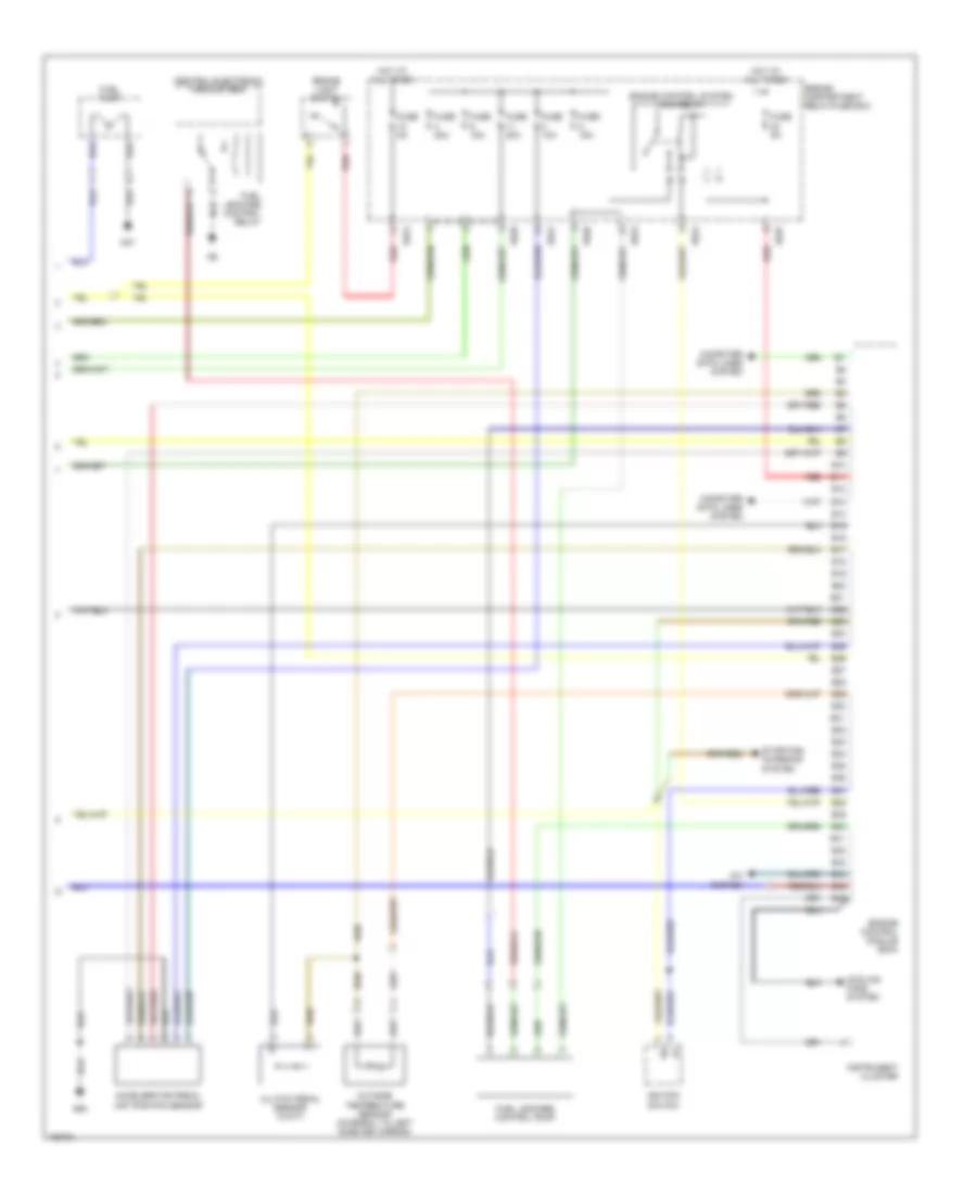
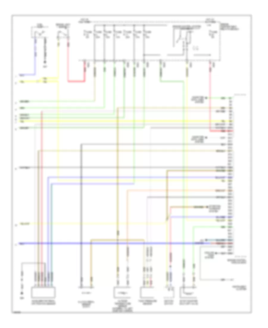
2.3L Turbo, Engine Performance Wiring Diagrams (3 of 3) for Volvo V70 T-5 2002
List of elements for 2.3L Turbo, Engine Performance Wiring Diagrams (3 of 3) for Volvo V70 T-5 2002:
- 15/20
- 15/23
- 15/24
- 15/25
- A/c system
- Accelerator pedal (ap) position sensor
- B10
- B11
- B12
- B13
- B14
- B15
- B16
- B17
- B18
- B19
- B20
- B21
- B22
- B23
- B24
- B25
- B26
- B27
- B28
- B29
- B30
- B31
- B32
- B33
- B34
- B35
- B36
- B37
- B38
- B39
- B40
- B41
- B42
- B43
- B44
- B45
- B46
- Brake light switch
- Central electronic module (cem)
- Clutch pedal sensor (w/m/t)
- Computer data lines system
- Cooling fans system
- Engine compartment relay/fuse box
- Engine control module (ecm)
- Engine control system main relay
- Fuel leakage control pump
- Fuel leakage control relay
- Fuel pump
- Fuse 10a
- Fuse 15a
- Fuse 20a
- Fuse 5a
- G47
- G93
- Hot at all times
- Ignition switch
- Instrument cluster
- Outside temperature sensor (integral to left sideview mirror)
- Red
- Starting/ charging system
2.4L
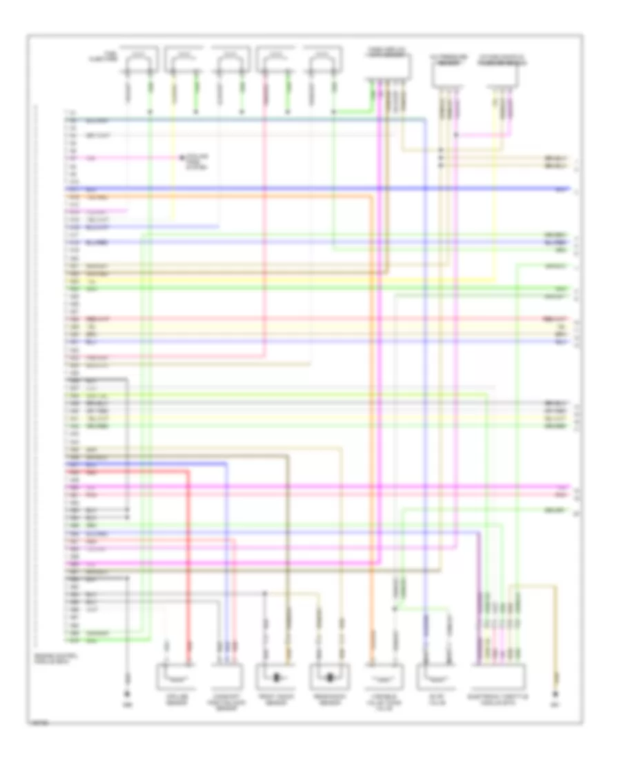
2.4L Turbo, Engine Performance Wiring Diagrams (1 of 3) for Volvo V70 T-5 2002
List of elements for 2.4L Turbo, Engine Performance Wiring Diagrams (1 of 3) for Volvo V70 T-5 2002:
- A/c pressure sensor
- A10
- A11
- A12
- A13
- A14
- A15
- A16
- A17
- A18
- A19
- A20
- A21
- A22
- A23
- A24
- A25
- A26
- A27
- A28
- A29
- A30
- A31
- A32
- A33
- A34
- A35
- A36
- A37
- A38
- A39
- A40
- A41
- A42
- A43
- A44
- A45
- A46
- A47
- A48
- A49
- A50
- A51
- A52
- A53
- A54
- A55
- A56
- A57
- A58
- A59
- A60
- A61
- A62
- A63
- A64
- A65
- A66
- A67
- A68
- A69
- A70
- Camshaft position (cmp) sensor
- Computer data lines system
- Cooling fans system
- Engine control module (ecm)
- Engine throttle body
- Evap valve
- Front knock sensor
- Fuel injectors
- G96
- Impulse sensor
- Intake air temperature sensor)
- Intake manifold pressure sensor
- Mass airflow (maf) sensor
- Pnk
- Rear knock sensor
- Red
- Variable valve timing valve
2.4L Turbo, Engine Performance Wiring Diagrams (2 of 3) for Volvo V70 T-5 2002
List of elements for 2.4L Turbo, Engine Performance Wiring Diagrams (2 of 3) for Volvo V70 T-5 2002:
- A20
- Air preheating ptc resistor
- B14
- B17
- B18
- B22
- C14
- Central electronic module (cem)
- Computer data lines system
- Coolant level sensor
- Coolant temperature sensor
- Data link connector (dlc)
- Fuel pump relay
- Fuse 10a
- Fuse 15a
- G88
- G89
- G91
- Heated oxygen sensor (ho2s) 1
- Heated oxygen sensor (ho2s) 2
- Hot at all times
- Ignition coils
- Oil pressure sensor
- Passenger compartment fuse box
- Pnk
- Red
- Spark plugs
- Transmission control module (tcm)
- Turbocharger control valve
2.4L Turbo, Engine Performance Wiring Diagrams (3 of 3) for Volvo V70 T-5 2002
List of elements for 2.4L Turbo, Engine Performance Wiring Diagrams (3 of 3) for Volvo V70 T-5 2002:
- 15/20
- 15/23
- 15/24
- 15/25
- A/c system
- Accelerator pedal (ap) position sensor
- B10
- B11
- B12
- B13
- B14
- B15
- B16
- B17
- B18
- B19
- B20
- B21
- B22
- B23
- B24
- B25
- B26
- B27
- B28
- B29
- B30
- B31
- B32
- B33
- B34
- B35
- B36
- B37
- B38
- B39
- B40
- B41
- B42
- B43
- B44
- B45
- B46
- Brake light switch
- Central electronic module (cem)
- Clutch pedal sensor (w/m/t)
- Computer data lines system
- Cooling fans system
- Engine compartment relay/fuse box
- Engine control module (ecm)
- Engine control system main relay
- Fuel leakage control pump
- Fuel leakage control relay
- Fuel pump
- Fuse 10a
- Fuse 15a
- Fuse 20a
- Fuse 5a
- G47
- G93
- Hot at all times
- Ignition switch
- Instrument cluster
- Outside temperature sensor (integral to left sideview mirror)
- Red
- Starting/ charging system
2.4L, Engine Performance Wiring Diagrams (1 of 3) for Volvo V70 T-5 2002
List of elements for 2.4L, Engine Performance Wiring Diagrams (1 of 3) for Volvo V70 T-5 2002:
- A/c pressure sensor
- A10
- A11
- A12
- A13
- A14
- A15
- A16
- A17
- A18
- A19
- A20
- A21
- A22
- A23
- A24
- A25
- A26
- A27
- A28
- A29
- A30
- A31
- A32
- A33
- A34
- A35
- A36
- A37
- A38
- A39
- A40
- A41
- A42
- A43
- A44
- A45
- A46
- A47
- A48
- A49
- A50
- A51
- A52
- A53
- A54
- A55
- A56
- A57
- A58
- A59
- A60
- A61
- A62
- A63
- A64
- A65
- A66
- A67
- A68
- A69
- A70
- Camshaft position (cmp) sensor
- Cooling fans system
- Electronic throttle module (etm)
- Engine control module (ecm)
- Evap valve
- Front knock sensor
- Fuel injectors
- G91
- G96
- Impulse sensor
- Intake manifold pressure sensor
- Mass airflow (maf) sensor
- Nca
- Pnk
- Rear knock sensor
- Red
- Variable valve timing valve
2.4L, Engine Performance Wiring Diagrams (2 of 3) for Volvo V70 T-5 2002
List of elements for 2.4L, Engine Performance Wiring Diagrams (2 of 3) for Volvo V70 T-5 2002:
- A20
- Air preheating ptc resistor
- B14
- B17
- B18
- B22
- C14
- Central electronic module (cem)
- Computer data lines system
- Coolant level sensor
- Coolant temperature sensor
- Data link connector (dlc)
- Fuel pump relay
- Fuse 10a
- Fuse 15a
- G88
- G89
- G91
- Heated oxygen sensor (ho2s) 1
- Heated oxygen sensor (ho2s) 2
- Hot at all times
- Ignition coils
- Oil pressure sensor
- Passenger compartment fuse box
- Pnk
- Red
- Spark plugs
- Transmission control module (tcm)
2.4L, Engine Performance Wiring Diagrams (3 of 3) for Volvo V70 T-5 2002
List of elements for 2.4L, Engine Performance Wiring Diagrams (3 of 3) for Volvo V70 T-5 2002:
- 15/20
- 15/23
- 15/24
- 15/25
- A/c system
- Accelerator pedal (ap) position sensor
- B10
- B11
- B12
- B13
- B14
- B15
- B16
- B17
- B18
- B19
- B20
- B21
- B22
- B23
- B24
- B25
- B26
- B27
- B28
- B29
- B30
- B31
- B32
- B33
- B34
- B35
- B36
- B37
- B38
- B39
- B40
- B41
- B42
- B43
- B44
- B45
- B46
- B47
- B48
- Brake light switch
- Clutch pedal sensor (w/m/t)
- Computer data lines system
- Cooling fans system
- Engine compartment relay/fuse box
- Engine control module (ecm)
- Engine control system main relay
- Evap canister shut-off valve
- Fuel pump
- Fuse 10a
- Fuse 15a
- Fuse 20a
- Fuse 5a
- G47
- G93
- Hot at all times
- Ignition switch
- Instrument cluster
- Outside temperature sensor (integral to left sideview mirror)
- Red
- Starting/ charging system
- Tank pressure sensor