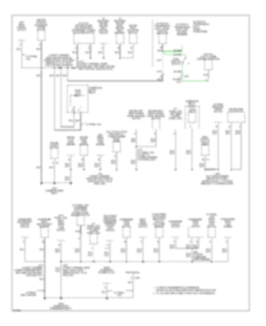
GROUND DISTRIBUTION
Ground Distribution Wiring Diagram (1 of 3) for Chevrolet HHR SS 2009

List of elements for Ground Distribution Wiring Diagram (1 of 3) for Chevrolet HHR SS 2009:
- (2.0l) engine control module
- (a/t) park/ neutral position (pnp) switch
- (a/t) transmission control module (tcm)
- (behind left end of dash) g201
- (except 2.0l) engine control module (ecm)
- (if equipped) personal audio link (pal) module
- (in steering column harness, behind inflatable restraint steering wheel module)
- (w/ active brake control & power brake system) traction control switch
- (w/ cigarette lighter ashtray) cigar lighter
- (w/o cigarette lighter ashtray) auxiliary power outlet
- 2.0l
- 87a
- A/c clutch diode 9
- A/c compressor clutch
- B x2
- B x3
- Battery
- Battery current sensor
- Body control module (bcm)
- Data link connector (dlc)
- E12 x4
- E6 x1
- Electronic brake control module (ebcm)
- Except 2.0l
- Fog lamp relay 54
- Fog lamp switch
- Fuel pump relay 19
- G103 (left front corner of engine compt)
- G107 (on front left corner of transmission)
- G108 (2.2l & 2.4l: right rear of engine block) (2.ol: right rear of engine)
- G109 (on left front shock tower)
- G111 (left side of engine compt)
- G203 (behind left end of dash)
- G403 (right rear corner of vehicle)
- Hazard switch
- Hood ajar switch
- Horn
- Horn switch
- Hvac control assembly
- I/p dimmer switch
- Ignition coil 1
- Ignition coil 2
- Ignition coil 3
- Ignition coil 4
- Inflatable restraint i/p module indicator
- Inflatable restraint steering wheel module coil
- Instrument panel cluster (ipc)
- J101 (in forward lamp harness, near left front headlamp, approximately 9 cm from breakout to g109)
- J103 (in engine harness, near left rear of engine, approximately 30 cm from breakout to heated oxygen sensor (ho2s) 1)
- J107 (in engine harness, near top of engine, approximately 6 cm from breakout to ignition coil 2 breakout)
- J112 (in body harness, 7.5 cm from g111 breakout)
- J195
- J200 (in i/p harness, near left side of i/p, approximately 29 cm from breakout to g203)
- J201 (in i/p harness, near center console, approximately 18 cm from breakout to inflatable restraint passenger air bag on/off indicator)
- J202
- Left front fog lamp
- Left front marker lamp
- Left headlamp
- Left park/ turn signal lamp
- Left steering wheel control switch
- Mass air flow (maf) sensor/ intake air tempe- rature (iat) sensor
- Power steering control module (pscm)
- Radio
- Rear defog relay 14
- Rear windshield wiper/washer switch
- Rear wpr relay 17
- Rear wsw relay 48
- Remote control door lock receiver (rcdlr)
- Right front fog lamp
- Right front marker lamp
- Right headlamp
- Right park/ turn signal lamp
- Right steering wheel control switch
- Run/ crank relay 51
- Steering wheel control) j208
- Theft deterrent module (tdm)
- Turbo charger boost gauge
- Turn signal/ multi-function switch
- Under- hood fuse block
- Underhood fuse block (in engine compt, next to left strut tower)
- W/ duke/ malta cloth trim
- Windshield wiper motor
- Wiper relay 70
- Wpr relay 52
- Wsw pump relay 39
- X1 d3
- X1 k
- X2 f9
- X2 k
- X3 c5
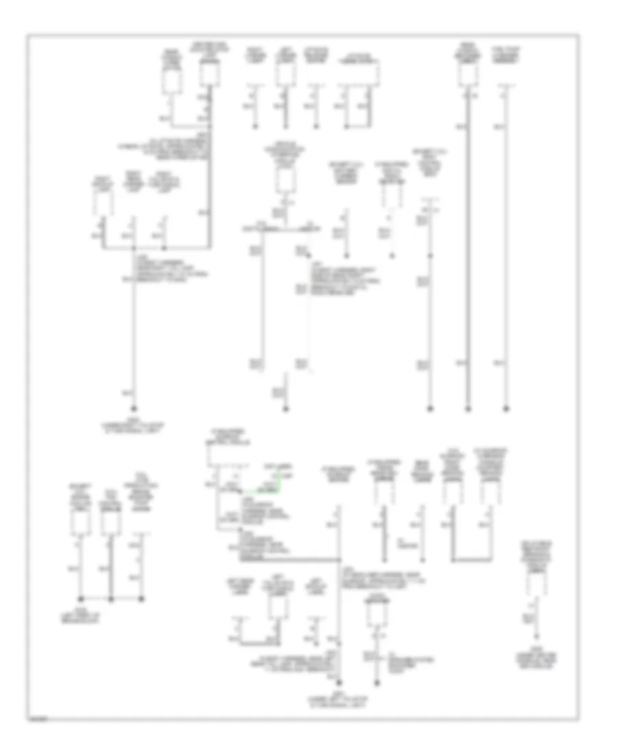
Ground Distribution Wiring Diagram (2 of 3) for Chevrolet HHR SS 2009
List of elements for Ground Distribution Wiring Diagram (2 of 3) for Chevrolet HHR SS 2009:
- (2.ol w/o multiple info display) turbocharger boost gage
- (if equipped) driver back heated seat element
- (if equipped) driver heated seat control module
- (if equipped) inflatable restraint vehicle rollover sensor
- (if equipped) rear view camera
- (in body harness, near center console, approximately 29 cm from breakout to a/t shift lock control solenoid) j300
- (w/ 6 way driver power adjuster seat) driver seat lumbar adjuster switch
- (w/ panel van) left rear access panel lock
- (w/ panel van) passenger right rear access panel release switch
- (w/ panel van) rear door lock switch
- (w/ panel van) right rear access panel lock
- (w/o panel van) right rear door jamb switch
- A x2
- Automatic transmission shift lever (if equipped)
- Automatic transmission shift lever position indicator
- Automatic transmission shift lock control solenoid
- Body control module (bcm)
- Brake fluid level switch
- C x406
- Center console accessory power outlet
- Chmsl relay
- Detector inflatable restraint sensor indicator
- Door lock relay
- Driver door jamb switch
- Driver door lock switch
- Driver left rear access panel release switch
- Driver right rear access panel release switch
- Driver seat adjuster switch
- Driver window switch
- G301 (under driver's seat)
- G302 (under front passenger's seat)
- Ignition lock cylinder control actuator
- Inflatable restraint passenger presence system (pps) module
- J301 (in body harness, near center console, approximately 29 cm from j300)
- J314 (in seat harness, under driver seat, between heated seat control module & c315)
- J315 (in seat harness, under passenger seat, between heated seat module & x314)
- J500 (in lf door harness, behind trim panel, approximately 17 cm from breakout to mirror motor)
- Left rear door jamb switch
- Left rear window switch
- Nca
- Outside rearview mirror switch
- Park position switch
- Passenger back heated seat element
- Passenger door jamb switch
- Passenger door lock switch
- Passenger heated seat control module
- Passenger window switch
- Provisional
- Rear accessory power outlet
- Right front door, approximately 18 cm from j307)
- Right rear window switch
- Underhood block relay
- Underhood relay block
- W/ front passenger/child presence
- W/ front seat heater
- W/ low risk deployment infant-only suppression
- W/ panel van
- W/o panel van
- X307 c
Ground Distribution Wiring Diagram (3 of 3) for Chevrolet HHR SS 2009
List of elements for Ground Distribution Wiring Diagram (3 of 3) for Chevrolet HHR SS 2009:
- (2.0l late production) brake booster pump motor
- (2.0l) fan control module
- (except 2.0l) battery current sensor
- (except 2.0l) body control module (bcm)
- (except 2.0l) engine cooling fan
- (if equipped) digital radio receiver
- (if equipped) inside rearview mirror
- (if equipped) sunroof control module
- (if equipped) sunroof switch
- (not used)
- (under center console, near sdm module)
- (w/ sunroof) overhead console courtesy, reading lamps
- (w/o sunroof) front dome/ reading lamps
- A x2
- Audio amplifier
- Center high mounted stop lamp (chmsl)
- Fuel pump & sender assembly
- G105 (left front of engine block)
- G306
- G401 (under left tail/stop & turn signal light)
- G402 (under right tail/stop & turn signal light)
- Inflatable restraint sensing & diagnostic module (sdm)
- J303 (in headliner harness, near sunroof, approximately 11 cm from breakout to x397)
- J400 (in body harness, near right tail lamp, approximately 27 cm from breakout to g402)
- J401 (in body harness, right side of rear compt, approximately 6 cm from breakout to digital radio receiver)
- J402 (in body harness, near left rear tail lamp, approximately 11 cm from g401 breakout)
- J900 (in liftgate harness, in rear liftgate, approximately 16 cm from breakout to rear wiper motor)
- Left backup lamp
- Left license lamp
- Left rear marker lamp
- Left tail/stop & turn signal lamp
- Liftgate door latch
- Liftgate release switch
- Nca
- Rear dome/ reading lamps
- Rear window defogger grid
- Rear window wiper motor
- Right backup lamp
- Right license lamp
- Right rear marker lamp
- Right tail/stop & turn signal lamp
- Vehicle communication interface module (vcim)
- W/ onstar
- W/ speaker system enhanced audio
- W/o digital radio
- X397