HORN
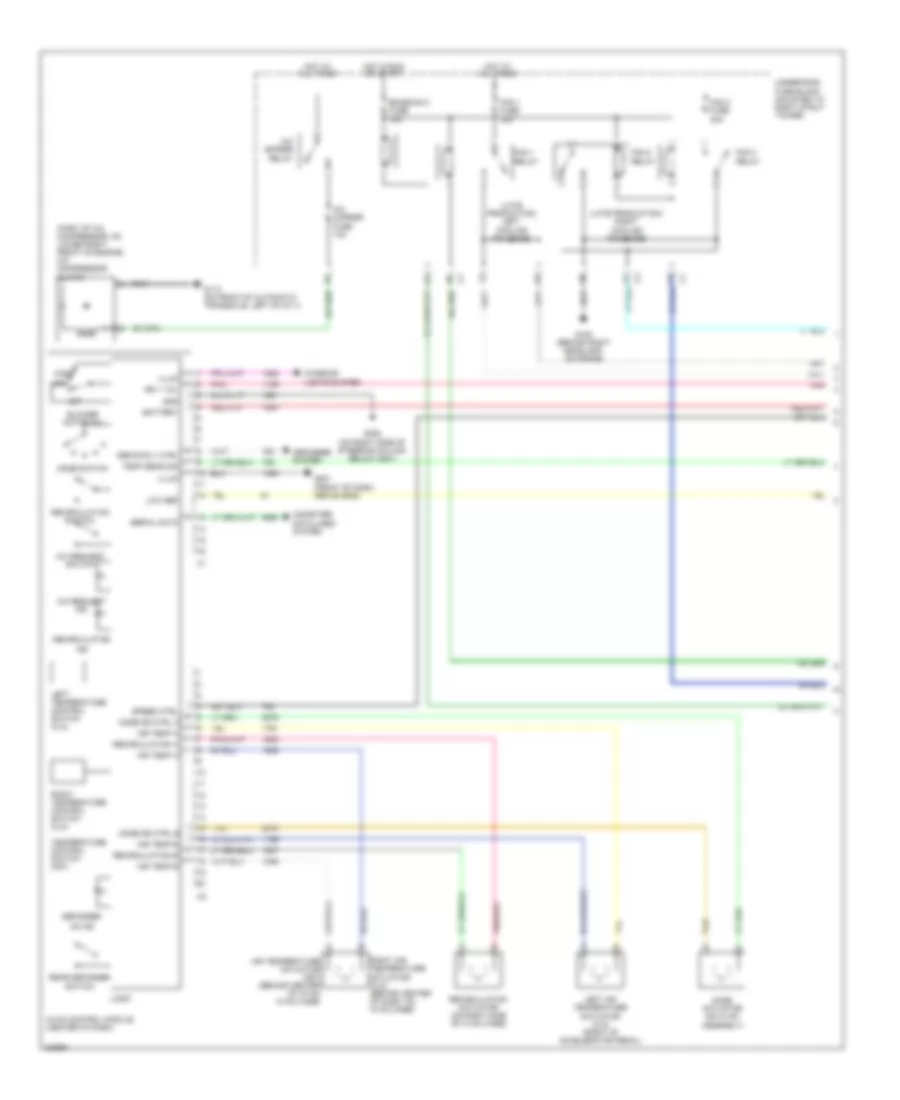
Horn Wiring Diagram for Chevrolet Suburban C1500 1993
List of elements for Horn Wiring Diagram for Chevrolet Suburban C1500 1993:
- (late production) left cooling fan diode
- (late production) right cooling fan diode
- (part of a/c compressor, on lower right front of engine) a/c compressor clutch
- A/c cmprsr fuse 10a
- A/c cmprsr relay
- A/c request ind
- A/c request switch
- Air temp a
- Air temp b
- Air temperature actuator (c67) (behind center of i/p on hvac case)
- Battery
- Blower motor sw
- Computer data lines system
- Defog rly ctrl
- Defogger
- Defogger system
- Emission 2 fuse 15a
- Fan 1 fuse 30a
- Fan 1 relay
- Fan 2 fuse 30a
- Fan 2 relay
- Fan 3 relay
- G100 (behind right headlamp, on frame)
- G113 (on front of automatic transaxle, left of g111)
- G201 (front of dash, above g202)
- G202 (on right side of steering column below c201)
- Gnd
- High
- Hot at all times
- Hot in run or start
- Hvac control module (center of dash)
- Ign 1 vol
- Illum
- Ind
- Interior lights system
- Left air temperature actuator (cj3) (right of accelerator pedal)
- Left temperature control switch (cj3)
- Logic
- Low
- Low ref
- Mode actuator (on hvac assembly)
- Mode dr ctrl a
- Mode dr ctrl b
- Mode switch
- Off
- On ind
- Pnk
- Rear defogger switch
- Recirculation
- Recirculation a
- Recirculation actuator (on right side of hvac case)
- Recirculation b
- Recirculation switch
- Right air temperature actuator (cj3) (behind center of dash, on hvac case)
- Right temperature control switch (cj3)
- Serial data
- Speed ctrl
- Tan
- Temp sens sig
- Temperature control switch (c67)
- Underhood fuse block (mounted to right strut tower)
 English