HORN
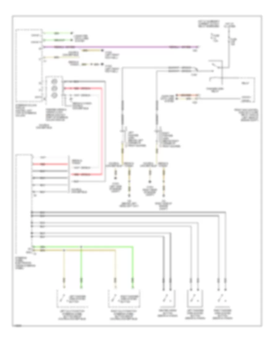
Horn Wiring Diagram for Mercedes-Benz E550 2014
List of elements for Horn Wiring Diagram for Mercedes-Benz E550 2014:
- (or red)
- C15m
- C22i
- C5c
- Can b h
- Can b l
- Can e1 h
- Can e1 l
- Center horns button (sedan & wagon)
- Computer data lines system
- Coupe & convertible
- Data
- Fanfare horn relay
- Fanfare horns & air bag clock spring contact (part of steering column module)
- Front sam control module w/ fuse/ relay module (left rear of engine compt)
- Fuse 31b 15a
- Fuse 7.5a
- Gnd
- Hot at all times
- Hot w/ quiescent current cutout relay energized
- Left fanfare horn (behind left corner of front bumper)
- Left fanfare horn system button
- Left fanfare horn system button (sedan & wagon)
- Left multi-function steering wheel button group (coupe & convertible)
- Red
- Relay
- Right fanfare horn (behind right corner of front bumper)
- Right fanfare horn system button
- Right fanfare horn system button (sedan & wagon)
- Right multi-function steering wheel button group (coupe & convertible)
- Sedan & wagon
- Sedan & wagon coupe & convertible
- Steering column module control unit (top of steering column)
- Steering wheel electronics (inside steering wheel)
- W15/5 (left front footwell)
- W16/3 (left side of engine compt)
- W16/4 (right rear of engine compt)
- W2 (right side of engine compt)
- W9 (behind left headlight unit)
 English