
HORN
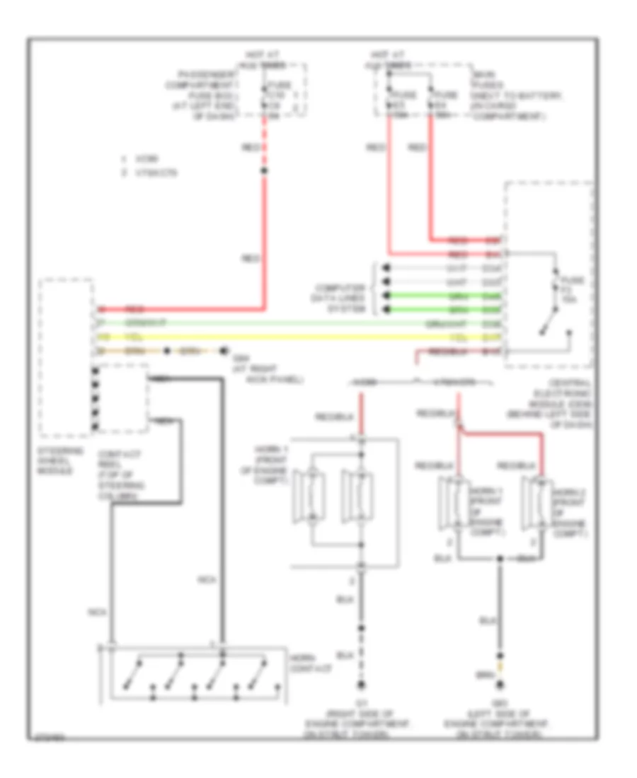
Horn Wiring Diagram for Volvo V70 2007
List of elements for Horn Wiring Diagram for Volvo V70 2007:
AIR CONDITIONINGBODY CONTROL MODULESANTI-THEFTANTI-LOCK BRAKESCOMPUTER DATA LINESCOOLING FANCRUISE CONTROLDEFOGGERSEXTERIOR LIGHTSGROUND DISTRIBUTIONELECTRONIC POWER STEERINGHEADLIGHTSELECTRONIC SUSPENSIONENGINE PERFORMANCEHORNMEMORY SYSTEMSINSTRUMENT CLUSTERPOWER MIRRORSINTERIOR LIGHTSPOWER SEATSPOWER WINDOWSPOWER DISTRIBUTIONSTARTING/CHARGINGPOWER DOOR LOCKSRADIOPOWER TOP/SUNROOFNAVIGATIONWARNING SYSTEMSSHIFT INTERLOCKSUPPLEMENTAL RESTRAINTSWIPER/WASHERTRANSMISSION