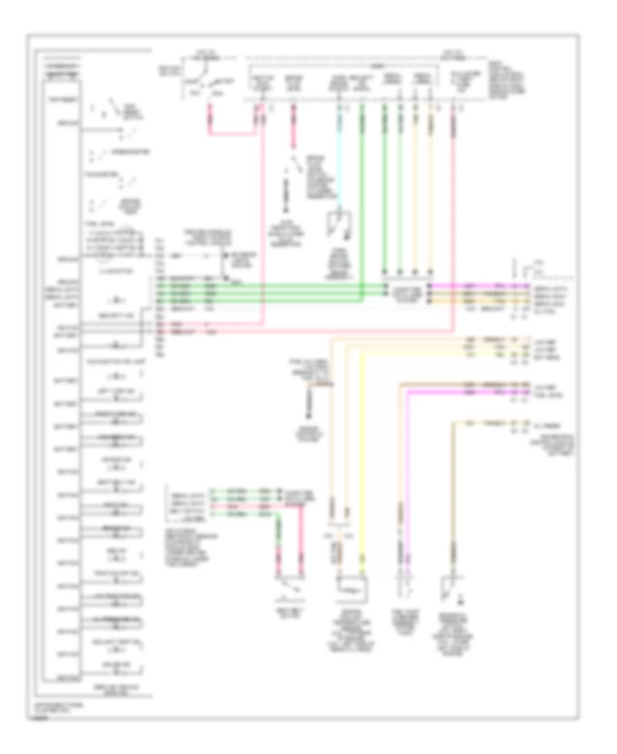
INSTRUMENT CLUSTER
Instrument Cluster Wiring Diagram for Chevrolet Malibu Maxx LT 2004
List of elements for Instrument Cluster Wiring Diagram for Chevrolet Malibu Maxx LT 2004:
- (center console, front of body control module)
- (fuel inj harn, 4 cm from breakout to fuel inj 3) s106
- 000000 trip
- 2.2l
- 3.5l
- Abs ind
- Acc
- Air bag ind
- Batt ind
- Battery
- Belt switch
- Body control module (bcm) (below right side of dash, near blower motor)
- Brake fluid level
- Brake fluid level switch (on brake master cylinder reservoir)
- Brake ind
- Cluster/ theft fuse 10a
- Computer data lines system
- Coolant temp ind
- Cruise ind
- Ect sens
- Engine controls system
- Engine coolant temp
- Engine coolant temperature sensor (2.2l: top rear of engine) (3.5l: left side of rear cyl head)
- Engine oil pressure switch (2.2l: right side of engine) (3.5l: lower left side of engine)
- Exterior lights system
- Fuel level
- Fuel pump & sender assembly (in fuel tank)
- G109 (near wind- shield wiper fluid reservoir)
- G201
- Ground
- High beam ind
- Hot at all times
- Ignition
- Ignition (run/ start)
- Ignition switch
- Illumination
- Inflatable restraint sensing & diagnostic module (sdm) (under center console, under the carpet)
- Instrument panel cluster (ipc)
- Left turn ind
- Logic
- Low ref
- Low traction ind
- Malfunction ind lamp
- Mil ctrl
- Off
- Oil press
- Oil pressure ind
- Park brake switch
- Park brake switch (on park brake assembly)
- Pnk
- Powertrain control module (in front of battery)
- Right turn ind
- Run
- Seat belt ind
- Seat belt switch
- Security ind
- Security ind signal
- Serial bus
- Serial bus +
- Serial bus -
- Serial data
- Service vehicle soon ind
- Speedometer
- Start
- Tachometer
- Tan
- Traction off ind
- Trip reset
- Trip reset switch
- Vf display
 English