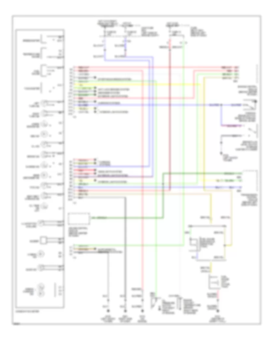
INSTRUMENT CLUSTER
Instrument Cluster Wiring Diagram for Subaru Impreza L 1997
List of elements for Instrument Cluster Wiring Diagram for Subaru Impreza L 1997:
- 1.8l
- 2.2l
- A10
- A11
- A12
- A13
- A14
- A15
- A16
- Abs ind
- Airbag warning ind
- Anti-lock brakes system
- B12
- B13
- B14
- B15
- B55
- B56
- B84
- Brake fluid level switch (in brake master cylinder)
- Brake ind
- Buzzer
- Charge ind
- Check engine ind
- Combination meter
- Cruise control module (behind center of dash)
- Defogger system
- Door ind
- Engine control module (behind center of dash)
- Engine coolant temperature sensor (right rear of engine)
- Exterior lights system
- F35
- Fuel gauge
- Fuel gauge sub module (near fuel tank)
- Fuel gauge unit (in fuel tank)
- Fuse 15 15a
- Fuse 25 10a
- Fuse 26 15a
- Fuse/ relay box (behind left side of dash)
- Fwd ind
- G102 (left shock tower)
- G121 (center of safety wall)
- G133 (on engine)
- G201 (right side of dash)
- Headlights system
- Hi beam ind
- Hot at all times
- Hot in on and start
- Hot with right headlight relay energized
- I10
- I12
- I13
- Illumination (5 bulbs)
- Interior lights system
- Left turn ind
- Main fuse box (left side of engine compt)
- Oil ind
- Oil pressure switch (top right front of engine)
- Oil temp ind (a/t)
- Parking brake switch (base of parking brake lever)
- Rear defogger ind
- Red
- Right turn ind
- Seat belt warning ind
- Speedometer
- Starting/charging system
- Tachometer
- Temperature gauge
- Transmission control module (behind left side of dash)
- Warning systems
 English