INSTRUMENT CLUSTER
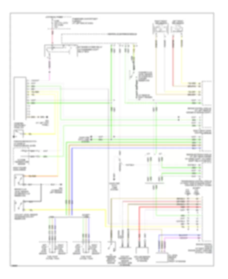
Instrument Cluster Wiring Diagram for Volvo V70 T-5 2004
List of elements for Instrument Cluster Wiring Diagram for Volvo V70 T-5 2004:
- (at rear of right fender) g1
- (in passenger compt relay box)
- (v70, xc70) (xc90)
- 2.4l non- turbo
- A/t
- Brake control module (at left rear of corner of engine compt)
- Brake fluid level sensor (on brake fluid reservoir)
- Central electronic module
- Combined instrument panel dim
- Computer data lines system
- Coolant level sensor (on engine coolant reservoir)
- Coolant temperature sensor (on right side of engine)
- Engine control module (at right side of engine compt, forward of strut tower)
- Except 2.4l non- turbo
- Except v70r
- Extended di-feed relay
- Fuel pump (in fuel tank)
- Fuse c24 c21 10a
- G83 (at left kick panel)
- G93 (at rear of left fender)
- Hot at all times
- Impulse sensor (on top rear of engine)
- Left front abs sensor
- Left pump fuel level sensor
- M/t
- Nca
- Oil level sensor (v70r) (front of engine)
- Oil pressure sensor (front of engine)
- Outside temperature sensor
- Parking brake switch (at base of parking brake lever)
- Passenger compartment fuse box (at left end of dash)
- Rear electronic module (at left rear corner of cargo compt, on cargo compt relay/fuse box)
- Red
- Right front abs sensor
- Right front door control module
- Right power door mirror
- Right pump fuel level sensor
- Transmission control module (at right side of engine compt, forward of strut tower)
- V70r
- Washer fluid level sensor (in windshield washer reservoir)
 English