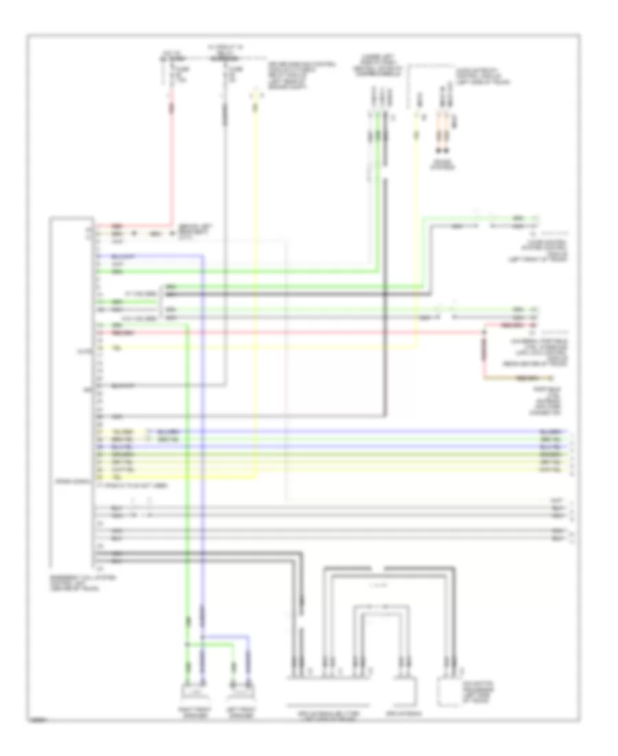
NAVIGATION
Auto Pilot System Wiring Diagram for Mercedes-Benz E320 2008

List of elements for Auto Pilot System Wiring Diagram for Mercedes-Benz E320 2008:
- (integral to interior rearview mirror) sound amplifier microphone
- (left rear wheelhousing) w6
- (or pnk)
- (pin 6-12 not used)
- (top right of tailgate) w8/5
- Amplifier module 1, screen antenna (wagon) (top right of tailgate)
- Antenna
- Audio gateway control module (left side of trunk)
- Aut
- Bass module loudspeaker
- C11
- C16
- C23
- C28
- Can-b h
- Can-b l
- Cd changer
- Center cockpit speaker (centerfill)
- Door speaker left front
- Door speaker right front
- Emergency call system control unit (center of trunk)
- Fuse 3 20a
- Fuse 40a
- Fuse 7.5a
- Gps ant
- Gps antenna
- Gps antenna splitter (left side of trunk)
- Hot at all times
- Interior fuse box (left end of dash)
- Left antenna amplifier module (left "c" pillar)
- Left rear door speaker
- Left rear surround loudspeaker
- Most
- Most in
- Most out
- Most wake-up
- Mute
- Navigation processor (left side of trunk)
- Nca
- Pnk
- Rear sam control module w/ fuse & relay module (left side of trunk)
- Red
- Right rear door speaker
- Right rear surround loudspeaker
- Sedan
- Shield
- Solid state
- Sound systems
- Tweeter
- W15/1 (near right kick panel)
- Wagon
- Wake-up
- Woofer
- Zf-out
COMAND Actuation Wiring Diagram, Early Production for Mercedes-Benz E320 2008
List of elements for COMAND Actuation Wiring Diagram, Early Production for Mercedes-Benz E320 2008:
- (or pnk)
- (pin 4-12 not used)
- Accept/ terminate phone call pushbutton
- Audio gateway control module (left side of trunk)
- Bass module loudspeaker
- Can-b h
- Can-b l
- Can-c h
- Can-c l
- Cd changer
- Central gateway control module (under left side of dash)
- Comand operating, display and control module
- Computer data lines system
- Data
- Fanfare horns & air bag clock spring contact (top of steering column)
- Fanfare horns pushbutton
- Fuse 15a
- Hot at all times
- Instrument cluster
- Interior fuse box (left end of dash)
- Left & right multi-function steering wheel pushbutton group
- Left fanfare horns pushbutton
- Left multi-function steering wheel pushbutton group
- Left rear surround loudspeaker
- Left voltage distributor (can) connector
- Most
- Most in
- Most out
- Most wake-up
- Navigation processor (left side of trunk)
- Nca
- Nf-l
- Nf-r
- Out
- Pnk
- Pushbutton
- Right fanfare horns pushbutton
- Right multi-function steering wheel pushbutton group
- Right rear surround loudspeaker
- Scroll forward/ back pushbutton
- Sdar control unit (right rear of trunk)
- Sedan
- Separation point
- Shield
- Steering column module (top of steering column)
- Steering wheel gear shift signal processing module (inside steering wheel)
- Steering wheel heater electronics (inside steering wheel)
- System selection pushbutton
- Universal portable ctel interface (upci [uhi]) control module (if equipped) (rear center of trunk)
- Voice control system control module (if equipped) (left front of trunk)
- Volume control
- W/ steering wheel gear shift
- W/ vcs & upci
- W/o steering wheel gear shift
- W/o vcs & upci
- W15/2 (left kick panel)
- Wagon
- Wake-up
- Wake-up signal connector
- Walkman nca
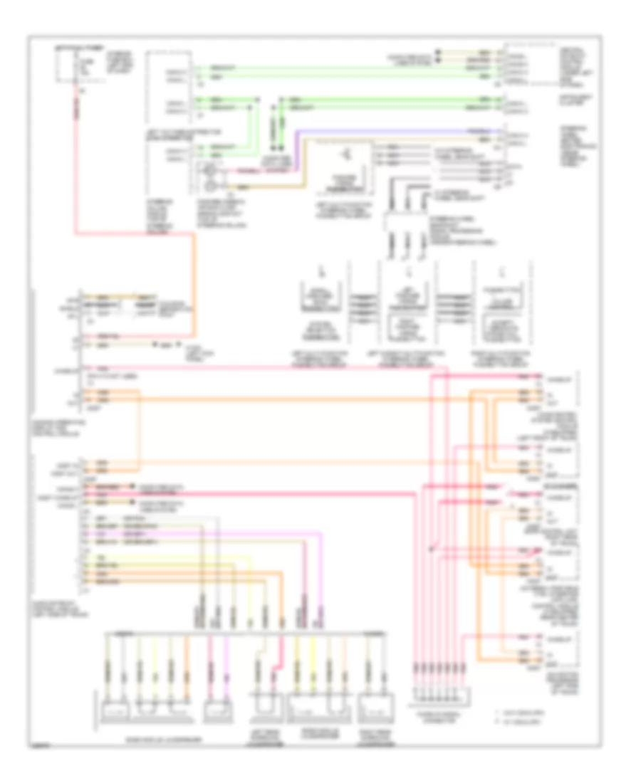
COMAND Actuation Wiring Diagram, Late Production (1 of 3) for Mercedes-Benz E320 2008
List of elements for COMAND Actuation Wiring Diagram, Late Production (1 of 3) for Mercedes-Benz E320 2008:
- (pin 1-8 not used)
- (pin 5-8 not used)
- (w/o sound system)
- - (pin 9-16 not used) ja
- Aux 1 left
- Aux 1 right
- C11
- C23
- C28
- Can-b h
- Can-b l
- Cellular phones system
- Center cockpit speaker (centerfill)
- Comand operating, display & control module
- Emergency call system control unit (center of trunk)
- Fuse 15a
- Fuse 7.5a
- Fw 1 am
- Fw 2
- Gnd
- Gps
- Hot at all times
- Interior fuse box (left end of dash)
- Left front door speaker group
- Left rear door speaker group
- Media interface connector1
- Mic 1 +
- Mic 2 +
- Micro out +
- Micro out -
- Most in
- Most uot
- Most wakeup
- Nca
- Pnk
- Rear sam control module w/ fuse & relay module (left side of trunk)
- Right front door speaker group
- Right rear door speaker group
- Shield
- Tweeter
- W/o sound system
- W15/2 (near left kick panel)
- Walkman separation point (w/ aux jack)
- Woofer
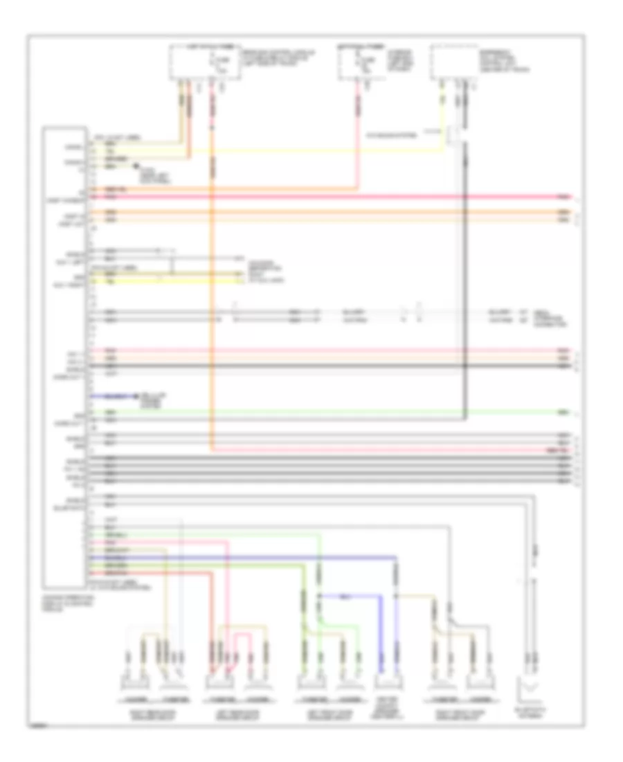
COMAND Actuation Wiring Diagram, Late Production (2 of 3) for Mercedes-Benz E320 2008
List of elements for COMAND Actuation Wiring Diagram, Late Production (2 of 3) for Mercedes-Benz E320 2008:
- Amplifier for sound system (if equipped)
- Amplifier module 1, screen antenna (top right of tailgate)
- Amplifier module 2, screen antenna
- Fiber optical cable connector (most)
- Gps antenna splitter (left side of trunk)
- Hands-free system microphone group
- Left antenna amplifier module (left 'c' pillar)
- Media interface control unit (if equipped)
- Most
- Most in
- Most out
- Most wakeup c1
- Nca
- Out
- Pnk
- Roof antenna
- Sdar control unit (w/ sdar) high-defination tuner control unit (w/ high- defination tuner) (sdar control unit: c1 right rear of trunk)
- Sedan
- Wagon
- Wake-up
- Wake-up signal connector
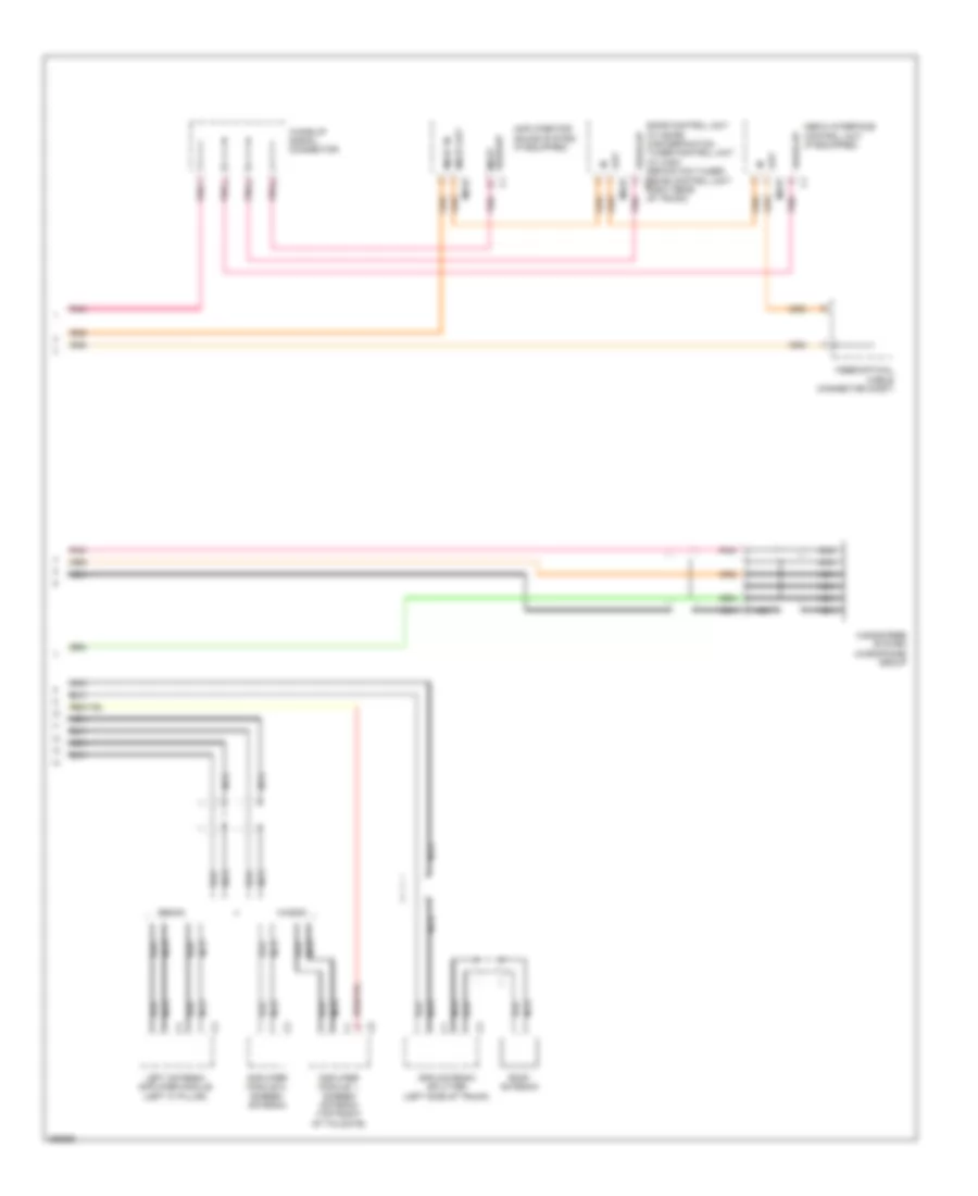
COMAND Actuation Wiring Diagram, Late Production (3 of 3) for Mercedes-Benz E320 2008
List of elements for COMAND Actuation Wiring Diagram, Late Production (3 of 3) for Mercedes-Benz E320 2008:
- (under left side of dash) central gateway control module
- Accept/ terminate phone call pushbutton
- Can-b h
- Can-b l
- Can-c h
- Can-c l
- Computer data lines system
- Fanfare horns & airbag clock spring contact (top of steering column)
- Instrument cluster
- Left multi-function steering wheel pushbutton group
- Left voltage distributor (can) connector
- Pushbutton
- Red
- Right multi-function steering wheel pushbutton group
- Scroll forward/ back pushbutton
- Steering column module (top of steering column)
- Steering wheel gear shift signal processing module (inside steering wheel)
- System selection pushbutton
- Volume control
- W/ steering wheel gear shift
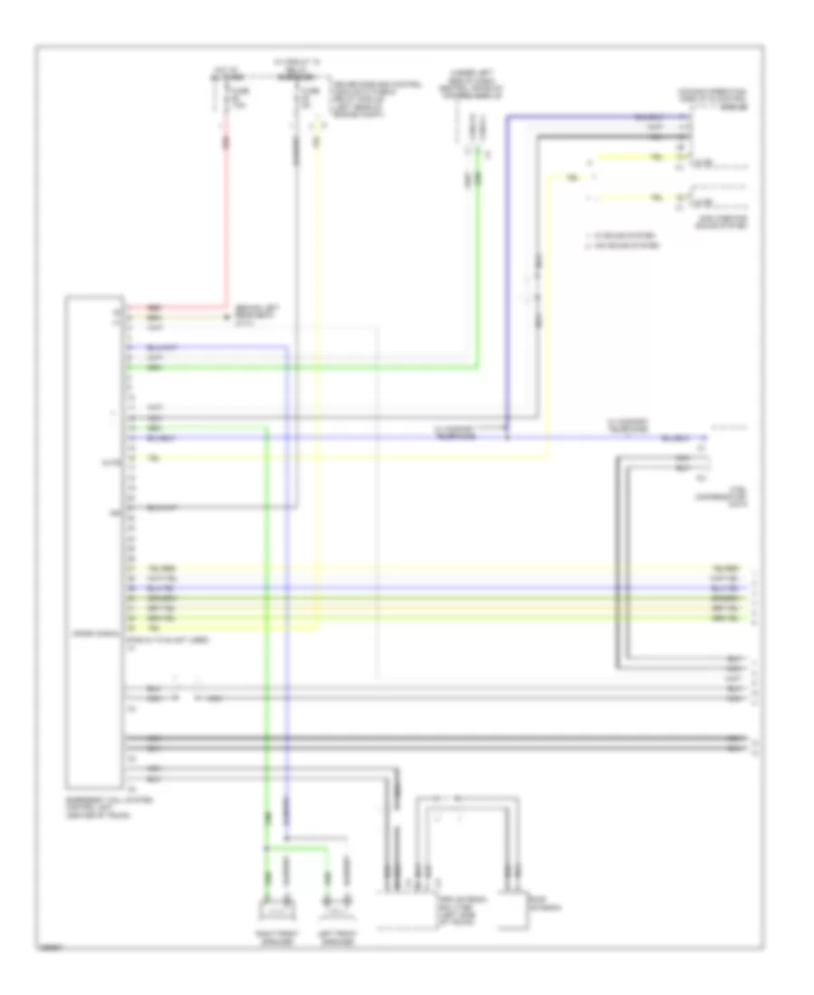
Navigation Wiring Diagram for Mercedes-Benz E320 2008
List of elements for Navigation Wiring Diagram for Mercedes-Benz E320 2008:
- (if equipped)
- (left front of trunk)
- (or pnk)
- (pin 6-12 not used)
- Audio gateway control module (left side of trunk)
- Bass module loudspeaker
- C16
- Can- b h
- Can- b l
- Can-b h
- Can-b l
- Can-c h
- Can-c l
- Cd changer
- Computer data lines system
- Emergency control unit call system (center of trunk)
- Fuse 20a
- Gps ant
- Gps antenna
- Gps antenna splitter (left side of trunk)
- Hot at all times
- Left front door contact switch (left "b" pillar)
- Left rear surround loudspeaker
- Me-sfi (me) control module (center rear of engine compt)
- Most
- Most in
- Most out
- Most wake-up
- Navigation processor (cns) (left side of trunk)
- Nca
- Out
- Pnk
- Radio control panel and navigation unit or (w/ radio & aps) comand operating, display and control module (w/ comand)
- Rear sam control module w/ fuse & relay module (left side of trunk)
- Right rear surround loudspeaker
- Sdar control unit (right rear of trunk)
- Sedan
- Shield
- Solid state
- Universal portable ctel interface (upci [uhi]) control module (if equipped) (rear center of trunk)
- Voice control system control module
- W/ command
- W/ radio & aps
- W/ vcs or upci
- W/o vcs or upci
- W15/2 (near left kick panel)
- W6 (left rear wheelhousing)
- Wagon
- Wake-up
- Wake-up signal connector
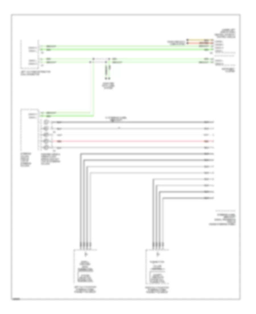
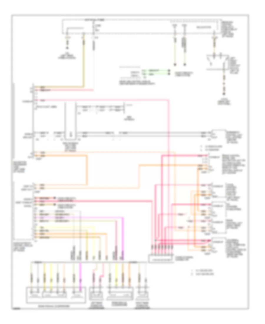
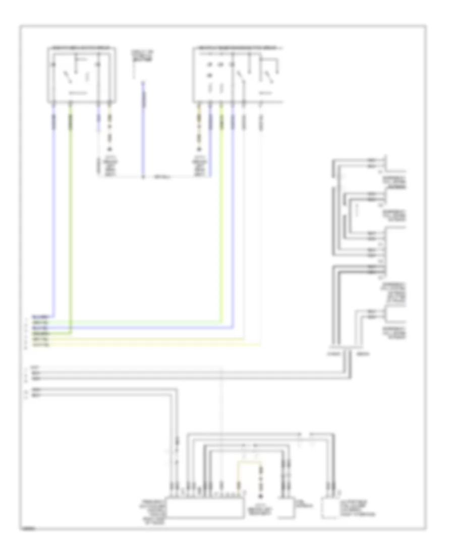
Parktronic Wiring Diagram, Early Production for Mercedes-Benz E320 2008
List of elements for Parktronic Wiring Diagram, Early Production for Mercedes-Benz E320 2008:
- (+) sh
- (+) sv
- (-) sh
- (-) sv
- C17
- Can-b h
- Can-b l
- Center instrument panel pts warning display
- Center left front pts ultrasonic sensor
- Center right front pts ultrasonic sensor
- Computer data lines system
- Fuse 20a
- Hot at all times
- Inner left front pts ultrasonic sensor
- Inner left rear pts ultrasonic sensor
- Inner right front pts ultrasonic sensor
- Inner right rear pts ultrasonic sensor
- Lower control field control module
- Out right rear pts ultrasonic sensor
- Outer left front pts ultrasonic sensor
- Outer left rear pts ultrasonic sensor
- Outer right front pts ultrasonic sensor
- Pnk
- Pts control module (left rear of trunk)
- Pts off switch
- Rear pts warning display
- Rear sam control module w/ fuse & relay module (left side of trunk)
- S1 v
- S10 h
- S2 v
- S3 v
- S4 v
- S5 v
- S6 v
- S7 h
- S8 h
- S9 h
- W h (+)
- W h (-)
- W h (data)
- W v (+)
- W v (-)
- W v (data)
- W6 (left rear wheelhousing)
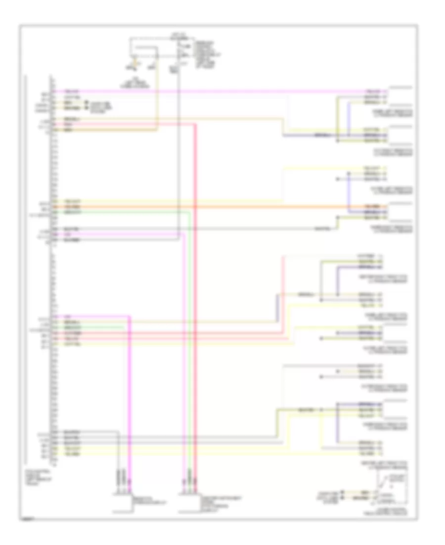
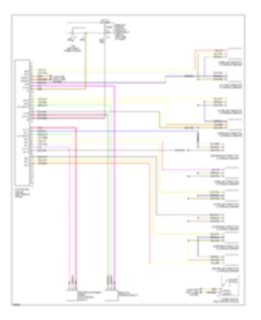
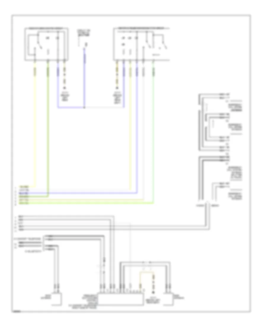
Parktronic Wiring Diagram, Late Production for Mercedes-Benz E320 2008
List of elements for Parktronic Wiring Diagram, Late Production for Mercedes-Benz E320 2008:
- (+) sh
- (-) sh
- C17
- Can-b h
- Can-b l
- Center instrument panel pts warning display
- Center left front pts ultrasonic sensor
- Center right front pts ultrasonic sensor
- Computer data lines system
- Fuse 20a
- Hot at all times
- Inner left front pts ultrasonic sensor
- Inner left rear pts ultrasonic sensor
- Inner right front pts ultrasonic sensor
- Inner right rear pts ultrasonic sensor
- Lower control field control module
- Out right rear pts ultrasonic sensor
- Outer left front pts ultrasonic sensor
- Outer left rear pts ultrasonic sensor
- Outer right front pts ultrasonic sensor
- Pnk
- Pts control module (left rear of trunk)
- Pts off switch
- Rear pts warning display
- Rear sam control module w/ fuse & relay module (left side of trunk)
- S1 v
- S10 h
- S2 v
- S3 v
- S4 v
- S5 v
- S6 v
- S7 h
- S8 h
- S9 h
- Sv (+)
- Sv (-)
- W h (+)
- W h (-)
- W h (data)
- W v (+)
- W v (-)
- W v (data)
- W6 (left rear wheelhousing)
Tele Aid Wiring Diagram, Early Production (1 of 2) for Mercedes-Benz E320 2008
List of elements for Tele Aid Wiring Diagram, Early Production (1 of 2) for Mercedes-Benz E320 2008:
- (behind left rear seat) w17/1
- (pins 34 to 54 not used)
- (under left side of dash) central gateway control module
- 15r
- Audio gateway control module (left side of trunk)
- Can-d h
- Can-d l
- Crash signal
- Driver side sam control module w/ fuse & relay module (left rear of engine compt)
- Emergency call system control unit (center of trunk)
- Fuse 5a
- Fuse 7.5a
- Gps antenna
- Gps antenna splitter (left side of trunk)
- Hot at all times
- Left front speaker
- Most
- Most in
- Most out
- Mute
- Navigation processor (left side of trunk)
- Nca
- Portable ctel antenna amplifier connector
- Red
- Right front speaker
- Shield
- Sound systems
- Universal portable ctel interface (upci (uhi)) control module (rear center of trunk)
- Voice control system control module (left front of trunk)
- W/ circuit 15 relay energized
- W/ vcs (sbs)
- W/o vcs (sbs)
Tele Aid Wiring Diagram, Early Production (2 of 2) for Mercedes-Benz E320 2008
List of elements for Tele Aid Wiring Diagram, Early Production (2 of 2) for Mercedes-Benz E320 2008:
- Circuit 15d potential splitter
- Ctel antenna
- Emergency call spare antenna
- Emergency call system antenna splitter (in trunk)
- Frequency switchover control module (right side of trunk)
- Kom
- Lct
- Mb-info & telediagnosis button group
- Nca
- Sedan
- Sos/ata (edw) switch group
- Uhi portable ctel holder (universal handy interface)
- W17/1 (behind left rear seat)
- Wagon
Tele Aid Wiring Diagram, Late Production (1 of 2) for Mercedes-Benz E320 2008
List of elements for Tele Aid Wiring Diagram, Late Production (1 of 2) for Mercedes-Benz E320 2008:
- (behind left rear seat) w17/1
- (pins 34 to 54 not used)
- (under left side of dash) central gateway control module
- 15r
- Amplifier for sound system
- Can-d h
- Can-d l
- Comand operating, display & control module
- Crash signal
- Ctel compensator, data
- Driver side sam control module w/ fuse & relay module (left rear of engine compt)
- Emergency call system control unit (center of trunk)
- Fuse 5a
- Fuse 7.5a
- Gps antenna splitter (left side of trunk)
- Hot at all times
- Left front speaker
- Mute
- Nca
- Red
- Right front speaker
- Roof antenna
- W/ circuit 15 relay energized
- W/ comfort telephone
- W/ sound system
- W/o sound system
Tele Aid Wiring Diagram, Late Production (2 of 2) for Mercedes-Benz E320 2008
List of elements for Tele Aid Wiring Diagram, Late Production (2 of 2) for Mercedes-Benz E320 2008:
- 58d
- Circuit 15d potential splitter
- Emergency call spare antenna
- Emergency call system antenna splitter (in trunk)
- Frequency switchover control module (w/ comfort telephone) (right side of trunk)
- Mb-info & telediagnosis button group
- Nca
- Roof antenna
- Sedan
- Sos/ata (edw) switch group
- W/ comfort telephone
- W17/1 (behind left rear
- W17/1 (behind left rear seat)
- Wagon
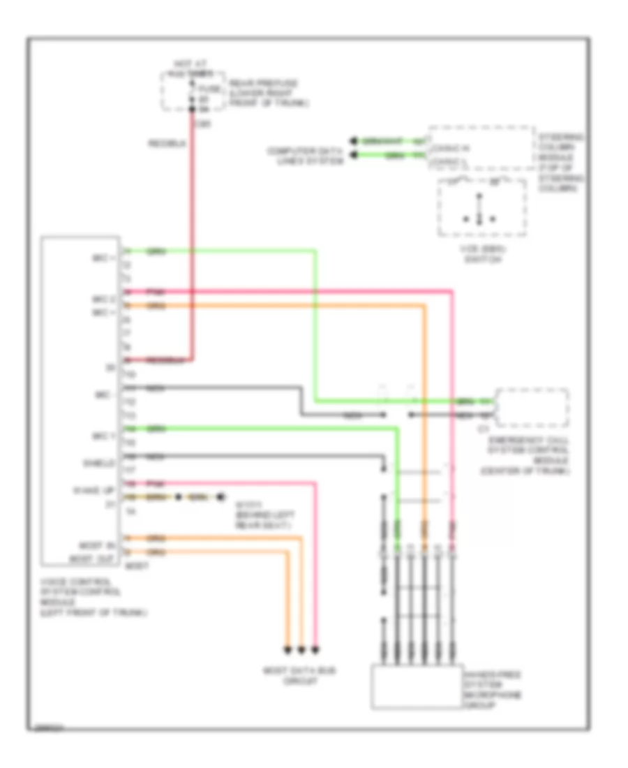
Voice Activation Wiring Diagram for Mercedes-Benz E320 2008
List of elements for Voice Activation Wiring Diagram for Mercedes-Benz E320 2008:
- C85
- Can-c h
- Can-c l
- Computer data lines system
- Emergency call system control module (center of trunk)
- Fuse 5a
- Hands-free system microphone group
- Hot at all times
- Mic +
- Mic -
- Mic 1
- Mic 2
- Most
- Most data bus circuit
- Most in
- Most out
- Nca
- Pnk
- Rear prefuse (lower right front of trunk)
- Shield
- Steering column module (top of steering column)
- Vcs (sbs) switch
- Voice control system control module (left front of trunk)
- W17/1 (behind left rear seat)
- Wake up