POWER DISTRIBUTION
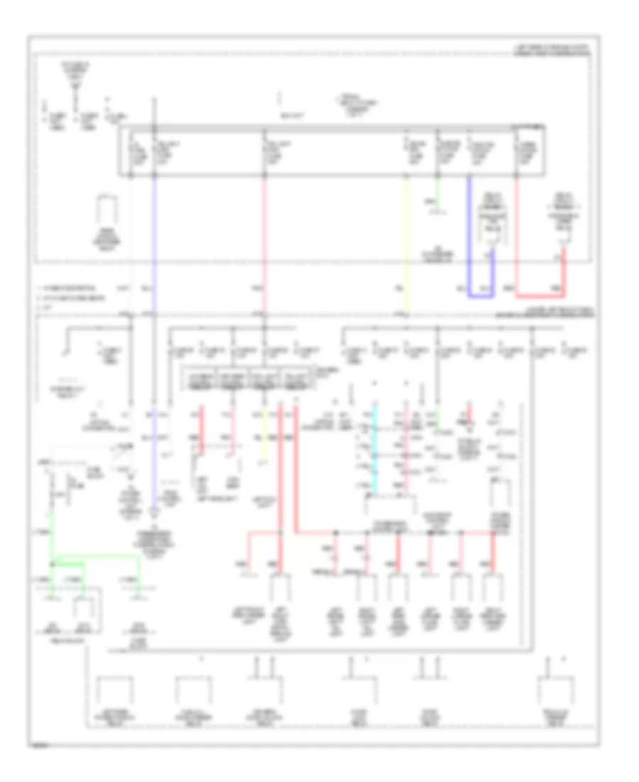
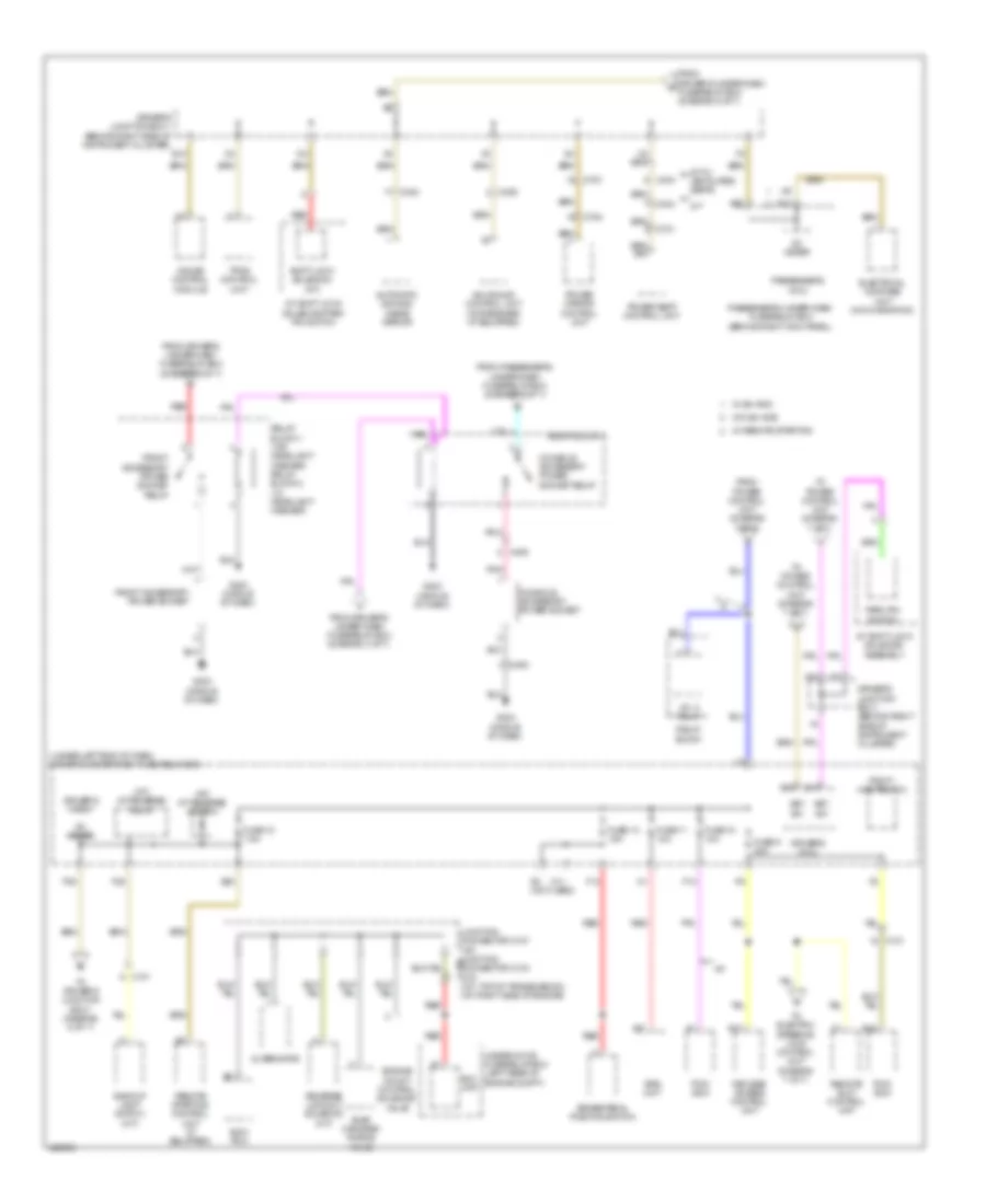
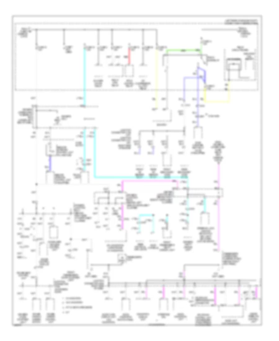
Power Distribution Wiring Diagram, with Keyless Access (1 of 7) for Acura TL 2014

List of elements for Power Distribution Wiring Diagram, with Keyless Access (1 of 7) for Acura TL 2014:
- (behind right kick panel) passenger's under-dash fuse/relay box
- (left rear of engine compt) under-hood fuse/relay box
- (not used)
- (under left end of dash) keyless access junction box
- +b cut relay (m/t)
- +b hazard
- +b rr fog
- A/t
- A/t w/ ventilated seats
- A10
- A18
- A21
- A26
- A27
- A28
- A31
- Abs/ vsa fuse 30a
- Abs/vsa mtr fuse 40a
- Alternator
- As f/b option fuse 40a
- As f/b std fuse 40a
- Battery
- Battery fuse 120a
- Battery sensor
- Brake pedal position switch
- C201
- C205
- C301
- C302
- C303
- C304
- C404
- C509
- C602
- C701
- C702
- C761
- D15
- Door lock relay
- Door unlock relay
- Driver's lumbar support switch
- Driver's micu
- Driver's seat heater relay (high)
- Driver's seat heater relay (low)
- Driver's seat heater relay box
- Driver's under-dash fuse/relay box (under left end of dash)
- E13
- Eps control unit
- Eps fuse 70a
- F15
- F32
- Front passenger's power seat adjustment switch
- Front passenger's power window switch
- Front passenger's seat heater relay (low)
- Front passenger's seat heater relay box
- Front passenger's seat relay (high)
- Fuse (not used)
- Fuse 10 10a
- Fuse 10 20a
- Fuse 11 20a
- Fuse 12 10a
- Fuse 12 7.5a
- Fuse 13 15a
- Fuse 13 20a
- Fuse 15 20a
- Fuse 16 15a
- Fuse 17 (not used)
- Fuse 18 7.5a
- Fuse 19 20a
- Fuse 20 (not used)
- Fuse 21 (not used)
- Fuse 22 (not used)
- Fuse 7 (not used)
- Fuse 8 20a
- Fuse 9 15a
- Fuse 9 20a
- H/l washer fuse 30a
- H10
- H20
- H28
- H38 (not used)
- Hazard warning switch/front passenger's air bag cut-off indicator
- Headlight washer motor relay (if equipped)
- Horn relay
- Ignition coil relay
- M/t
- Multi- fuse 1
- Multi-fuse 2
- Passenger's micu
- Red
- Relay block 1
- Relay block 2
- Relay block 3
- Relay circuit board
- Remote slot
- Remote slot control unit
- Right rear power window relay
- Seat ventilation relay
- Sh- awd fuse 30a
- Sh-awd relay (if equipped)
- Starter
- Starter solenoid
- Stereo amplifier
- T101
- T102
- To eld unit (diagram 2 of 7)
- To fuse 11 (diagram 3 of 7)
- To power control unit (diagram 7 of 7)
- To relay block 1 (diagram 6 of 7)
- Vsa modulator control unit
- W/ ventilated seats
- W/o ventilated seats
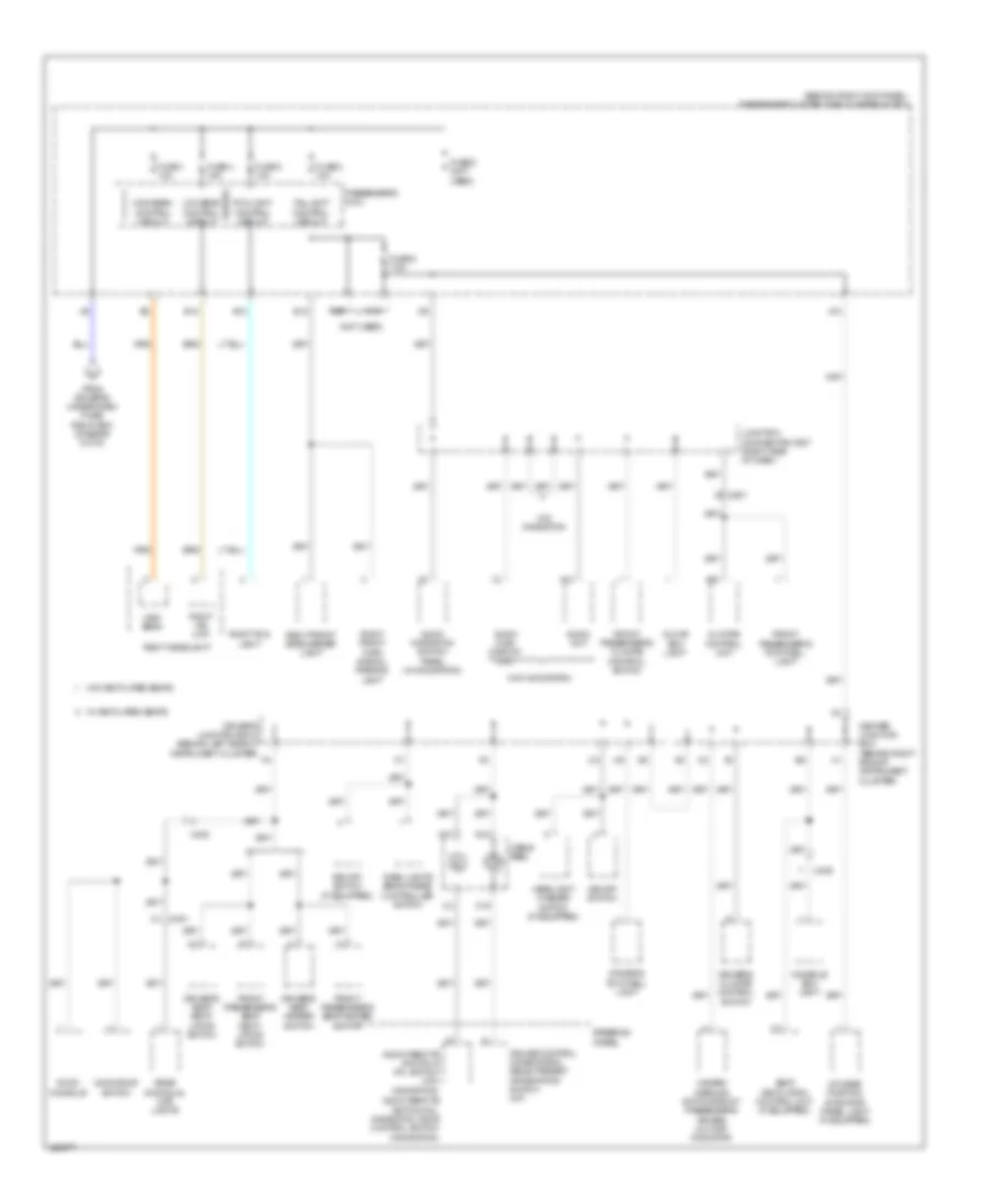
Power Distribution Wiring Diagram, with Keyless Access (2 of 7) for Acura TL 2014
List of elements for Power Distribution Wiring Diagram, with Keyless Access (2 of 7) for Acura TL 2014:
- (diagram 1 of 7)
- (left rear of engine compt) under-hood fuse/relay box
- (not used)
- (option connector)
- (under left end of dash) driver's under-dash fuse/relay box
- 40a
- A/c condenser fan relay
- A/t w/ ventilated seats
- As light main fuse 30a
- C402
- C404
- C451
- C701
- C751
- C753
- Control circuit
- D11
- Door lock relay
- Door unlock relay
- Dr f/b std fuse 60a
- Dr light main fuse 30a
- Driver's door unlock relay
- Driver's micu
- E11
- Eld unit
- F10
- F13
- F16
- F17
- F18
- F19
- F21
- Fog light
- From multi-fuse 1 a
- Fuel fill door opener relay
- Fuse 14 (not used)
- Fuse 19 20a
- Fuse 20 20a
- Fuse 21 20a
- Fuse 22 20a
- Fuse 23 15a
- Fuse 24 20a
- Fuse 25 15a
- Fuse 26 10a
- Fuse 27 10a
- Fuse 28 10a
- Fuse 29 7.5a
- Fuse 30 15a
- Fuse 31 (not used)
- Fuse 4 40a
- Fuse 5 (not used)
- Fuse 6 (not used)
- Fuse block
- G12
- H10
- High beam
- Ig fuse
- Ig main fuse 50a
- Ig1a relay
- Ig1b relay
- Ig2 relay
- Left brake light/ tail light
- Left fog light
- Left front side marker light
- Left front turn signal/ parking light
- Left headlight
- Left hid unit
- Left license plate light
- Left rear power window relay
- Left rear side marker light
- Low beam
- M/t
- Main fan motor fuse 30a
- Moonroof control unit/ motor
- Multi-fuse 3
- N10
- N14
- P11
- P12
- Pnk
- Power seat control unit
- Power window master switch
- Radiator fan
- Rear window defogger relay
- Red
- Relay
- Relay block
- Relay circuit board
- Right brake light/ tail light
- Right license plate light
- Right rear side marker light
- Starter cut relay 1
- Sub fan motor fuse 30a
- Taillight
- To fuse 15 (diagram 3 of 7)
- To passenger's under-dash fuse/relay box (diagram 4 of 7)
- To power control unit (diagram 7 of 7)
- To relay block 1 (diagram 6 of 7)
- Tpms control unit
- Trunk lid opener relay
- W/ remote starting
- Windshield wiper relay
- Wiper motor fuse 30a
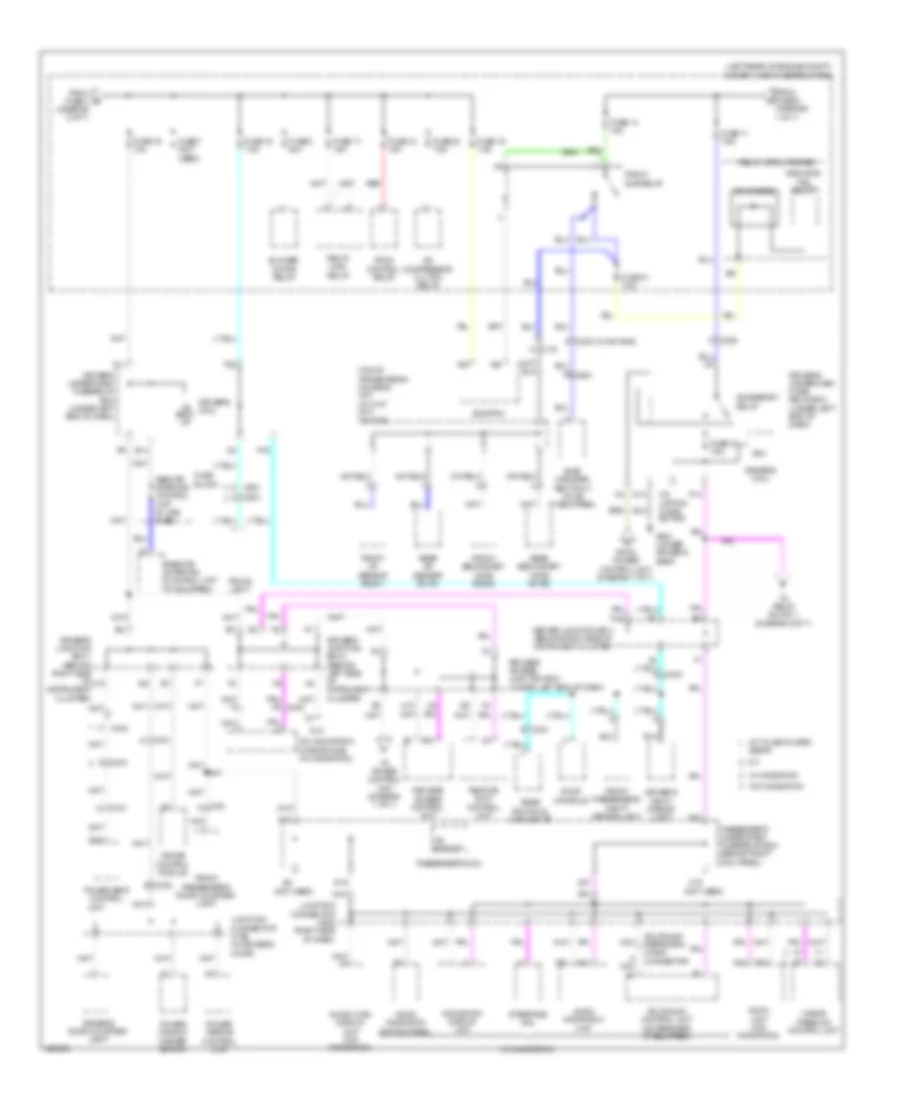
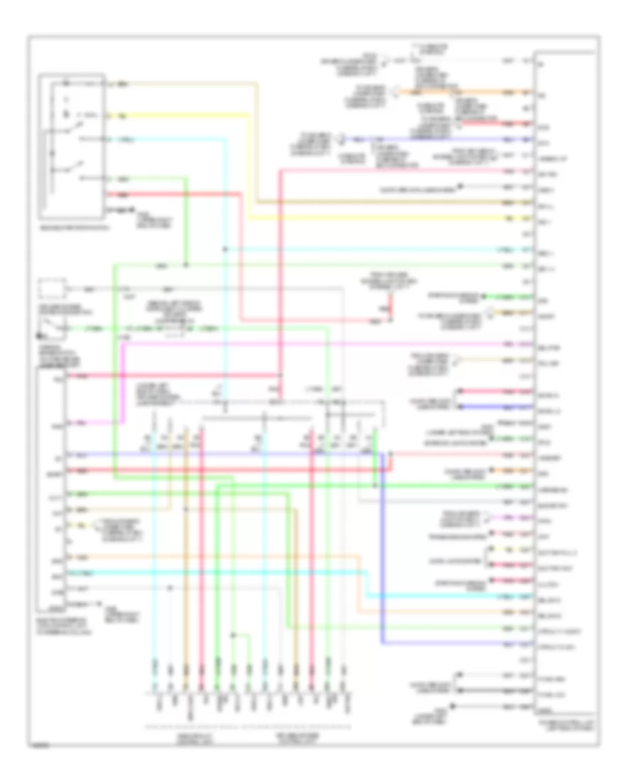
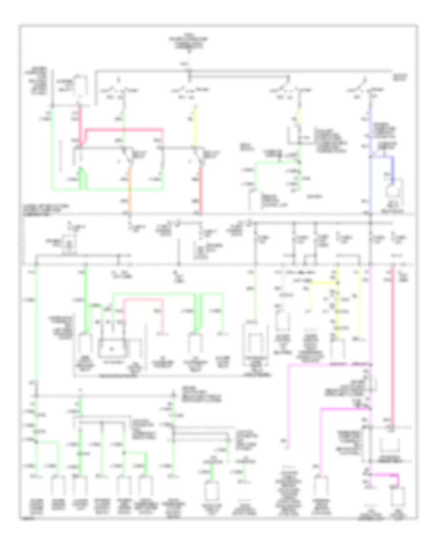
Power Distribution Wiring Diagram, with Keyless Access (3 of 7) for Acura TL 2014
List of elements for Power Distribution Wiring Diagram, with Keyless Access (3 of 7) for Acura TL 2014:
- (diagram 1 of 7)
- (diagram 2 of 7)
- (left rear of engine compt) under-hood fuse/relay box
- (not used)
- (top of transmission housing) (a/t) j/c c107 (m/t) j/c c106
- (w/ navigation)
- (w/ sh-awd)
- +b back up
- +b backup
- A/c compressor clutch relay
- A/c diode b
- A/t w/ ventilated seats
- A14
- A15
- A23
- A24
- A40
- Acc
- Accessory relay
- Acuralink control unit (xm receiver) (if equipped)
- Acuralink reprogra- mming connector
- Audio navigation switch panel
- Audio navigation unit
- Audio unit (w/o navigation)
- Audio-hvac display unit (w/o navigation)
- B10
- B36
- Blower motor relay
- C101
- C303
- C306
- C404
- C451
- C601
- C701
- C751
- C753
- C761
- Center junction box behind right side of instrument cluster
- D14
- D19
- D21
- Dlc
- Driver's door courtesy light
- Driver's junction box 1 (behind right side of instrument cluster)
- Driver's junction box 2 (behind left side of instrument cluster)
- Driver's micu
- Driver's under-dash fuse/ relay box (under left end of dash)
- Driver's under-dash fuse/relay box (under left end of dash)
- Driver's vanity mirror light
- E14
- Ecm/pcm
- Etcs control relay
- Evap canister vent shut valve (if equipped)
- F11
- F29
- From fuse 4 b
- From fuse 9 c
- From power control unit (diagram 7 of 7)
- Front a/f sensor (b2,s1)
- Front passenger's door courtesy light
- Front passenger's vanity mirror light
- Front secondary ho2s (b2,s2)
- Fuse 11 7.5a
- Fuse 14 15a
- Fuse 15 10a
- Fuse 16 7.5a
- Fuse 17 15a
- Fuse 18 15a
- Fuse 18 7.5a
- Fuse 19 7.5a
- Fuse 20 7.5a
- Fuse 21 7.5a
- Fuse 7 (not used)
- Fuse 8 40a
- Fuse block
- G601 (under driver's seat)
- Gauge control module
- H10
- H15
- H9 (option conn- ector)
- Hands freelink control unit
- Hfl-navigation microphone (w/ navigation)
- Interface dial
- Junction connector c508 (right side of dash)
- Junction connector c756 (in driver's door)
- K10
- Keyless access control unit
- Keyless access junction box (under left end of dash)
- M/t
- Navigation display unit
- P13
- P19
- Passenger's micu
- Passenger's under-dash fuse/relay box (behind right kick panel)
- Pgm-fi main relay
- Pgm-fi sub relay
- Power mirror control unit
- Power seat control
- Power window master switch
- Radiator fan relay
- Rear a/f sensor (b1,s1)
- Rear individual map lights
- Rear secondary ho2s (b1,s2)
- Red
- Relay circuit board
- Remote slot control unit
- Remote starting control unit (if equipped)
- Remote starting control unit in-line fuse
- Roof console
- To power control unit (diagram 7 of 7)
- To relay block 1 (diagram 6 of 7)
- Trunk light
- Unit
- W/ navigation
- W/o navigation
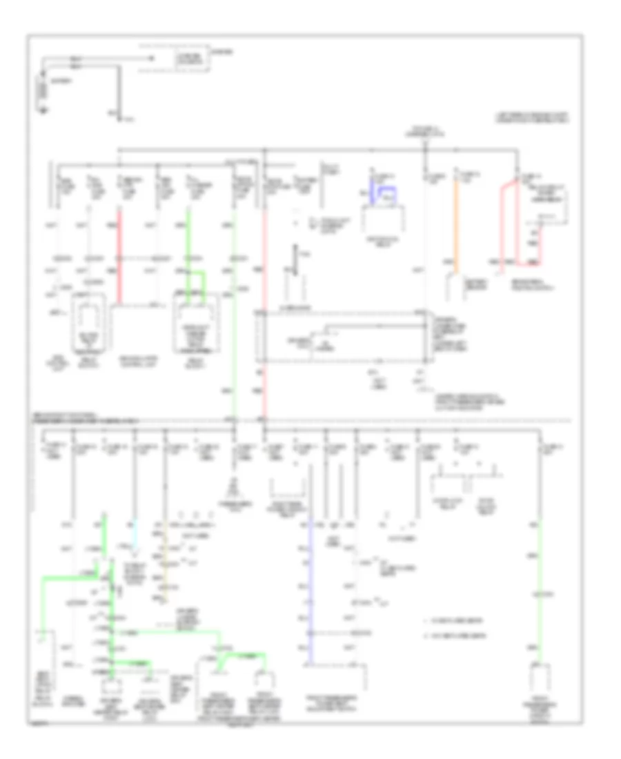
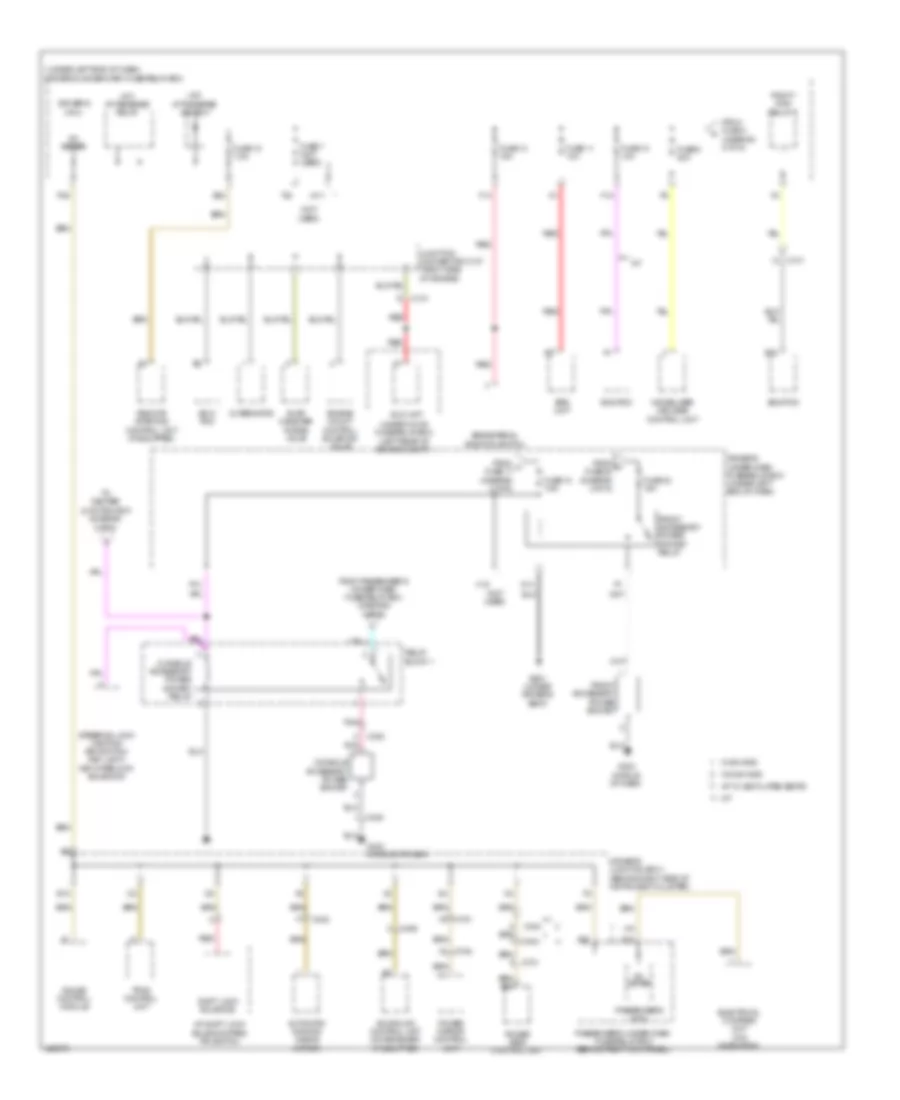
Power Distribution Wiring Diagram, with Keyless Access (4 of 7) for Acura TL 2014
List of elements for Power Distribution Wiring Diagram, with Keyless Access (4 of 7) for Acura TL 2014:
- (behind right kick panel) passenger's under-dash fuse/relay box
- (not used)
- (w/o navigation)
- A/t gear position indicator panel light (if equipped)
- A10
- A13
- A19
- A30
- Audio hvac display unit
- Audio navigation switch panel (w/ navigation)
- Audio remote switch & hfl-switch (w/o navigation) audio remote switch/hfl-
- Audio unit
- Bsi off switch (if equipped)
- C19
- C402
- C405
- C451
- C501
- Cable reel
- Center junction box (behind right side of instrument cluster)
- Climate control unit
- Console box light
- Control circuit
- Cruise control combination/ select/reset/ information switch (a/t)
- Dash lights brightness controller switch
- Driver's climate control switch
- Driver's footwell light
- Driver's junction box 2 (behind left side of instrument cluster)
- Driver's seat heater switch
- Driver's seat ventilation switch
- E10
- E12
- E13
- Fog light
- From driver's under-dash fuse/ relay box (diagram 2 of 7)
- Front passenger's climate control switch
- Front passenger's footwell light
- Front passenger's seat heater switch
- Front passenger's seat ventilation switch
- Fuse 1 10a
- Fuse 2 10a
- Fuse 3 10a
- Fuse 4 15a
- Fuse 5 (not used)
- Fuse 6 7.5a
- Glove box light
- H18
- H36
- Hazard warning switch/front passenger's air bag cut-off indicator
- Headlight washer switch (if equipped)
- High beam
- Junction connector c507 (right side of dash)
- Low beam
- Moonroof switch
- Navigation-voice control switch (w/ navigation)
- Passenger's micu
- Rear individual map lights
- Right fog light
- Right front side marker light
- Right front turn signal/ parking light
- Right headlight
- Right hid unit
- Roof console
- Seat ventilation control unit (if equipped)
- Steering wheel
- Taillight
- Vsa off switch
- W/ ventilated seats
- W/o navigation
- W/o ventilated seats
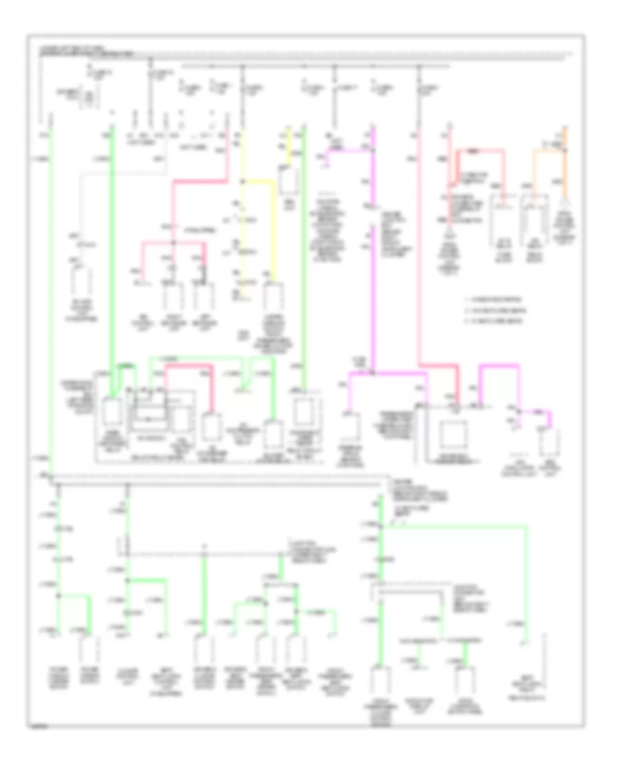
Power Distribution Wiring Diagram, with Keyless Access (5 of 7) for Acura TL 2014
List of elements for Power Distribution Wiring Diagram, with Keyless Access (5 of 7) for Acura TL 2014:
- (if equipped)
- (not used)
- (under left end of dash) driver's under-dash fuse/relay box
- A/c compressor clutch relay
- A/c condenser fan relay
- A/c diode a
- A/t
- A15
- A22
- A26
- Audio navigation switch panel
- Audio-hvac display unit
- B12
- Blower motor relay
- Bsi control unit
- C2 driver's under-dash fuse/relay box connector
- C403
- C404
- C406
- C410
- C702
- C752
- C753
- Center junction box (behind right side of instrument cluster)
- Climate control unit
- D16
- Driver's climate control switch
- Driver's micu
- Driver's seat heater switch
- Driver's seat ventilation switch
- E10
- Eps control unit
- F26
- F30
- Fan control relay
- From power control unit (diagram 7 of 7)
- Front passenger's climate control switch
- Front passenger's seat heater switch
- Front passenger's seat ventilation switch
- Fuse 1 7.5a
- Fuse 15 7.5a
- Fuse 16 7.5a
- Fuse 17
- Fuse 2 7.5a
- Fuse 3 20a
- Fuse 4 7.5a
- Fuse 5 7.5a
- Fuse 6 7.5a
- Fuse block
- G11
- G13
- Hazard warning switch/ front passenger's air bag cut-off indicator
- Ig1 b relay
- Ig2 day lt
- Ig2 relay
- Junction connector c408 (upper right side of dash)
- Junction connector c507 (behind right side of dash)
- Left bsi radar unit
- M/t
- N15
- Nca
- Ods unit
- P18
- Passenger's under-dash fuse/relay box (behind right kick panel)
- Pnk
- Power mirror switch
- Power window master switch
- Rear window defogger relay
- Red
- Relay block
- Relay block 2
- Relay circuit board
- Right bsi radar unit
- Seat ventilation control unit (if equipped)
- Seat ventilation relay
- Sh-awd control unit (if equipped)
- Srs unit
- Steering angle sensor (w/ sh-awd)
- Under-hood fuse/relay box (left rear of engine compt)
- Vsa modulator control unit
- W/ navigation
- W/ remote starting
- W/ sh- awd
- W/ ventilated seats
- W/o navigation
- W/o ventilated seats
- Windshield washer relay
- Windshield wiper relay
- Yaw rate lateral acceleration sensor (w/o sh-awd) yaw rate lateral/ longitudinal acceleration sensor (w/ sh-awd)
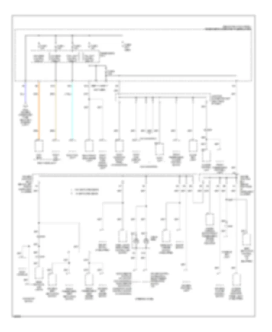
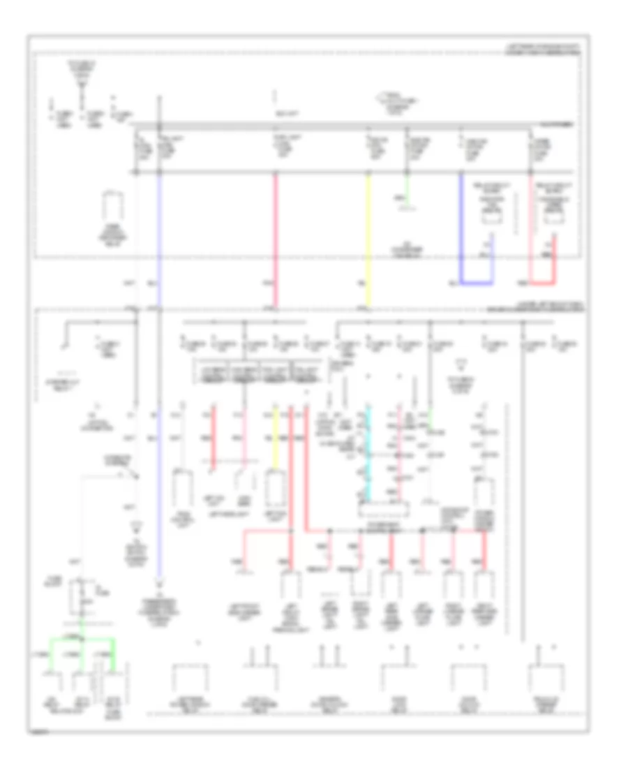
Power Distribution Wiring Diagram, with Keyless Access (6 of 7) for Acura TL 2014
List of elements for Power Distribution Wiring Diagram, with Keyless Access (6 of 7) for Acura TL 2014:
- (a/t) a/t reverse diode a
- (a/t) a/t reverse relay
- (not used)
- (under left end of dash) driver's under-dash fuse/relay box
- A/t
- A/t shift lock solenoid assembly
- A/t shift lock solenoid/park pin switch
- A/t w/ ventilated seats
- A27
- A35
- Acuralink control unit (xm receiver) (if equipped)
- Alternator
- Automatic dimming inside mirror
- B17
- B42
- Backup light switch (m/t)
- Brake pedal position switch
- C101
- C402
- C404
- C405
- C406
- C701
- C751
- C754
- Console accessory power socket
- Console accessory power socket relay
- Driver's junction box 1 (behind right side of instrument cluster)
- Driver's micu
- E10
- E20
- Ecm/ pcm
- Eld unit
- Electrical compass unit (w/o navigation)
- Engine mount control solenoid valve
- Evap canister purge valve
- F12
- F14
- F28
- From driver's under-dash fuse/relay box (diagram 2 of 7)
- From driver's under-dash fuse/relay box (diagram 3 of 7)
- From driver's under-dash fuse/relay box (diagram 6 of 7)
- From passenger's under-dash fuse/relay box (diagram 1 of 7)
- From power control unit (diagram 7 of 7)
- Front accessory power socket
- Front accessory power socket relay
- Fuse 10 10a
- Fuse 11 10a
- Fuse 12 7.5a
- Fuse 13 15a
- Fuse 9 20a
- G10
- G403 (middle of dash)
- Gauge control module
- Ig1 a relay
- Ig1 meter
- Junction connector c107 (a/t) junction connector c103 (m/t) c101 (m/t: top of transmission) (a/t: right side of engine)
- Key sw
- Keyless access control unit
- M/t
- N11
- P20
- Park pin switch
- Passenger's micu
- Passenger's under-dash fuse/relay box (behind right kick panel)
- Pcm/ ecm
- Pgm f1 main relay 2
- Pnk
- Power mirror control unit
- Power seat control unit
- Q13
- Q18
- Red
- Relay block
- Relay block 1
- Relay block 1 (w/o headlight washer) relay block 2 (w/ headlight washer)
- Remote slot control unit
- Remote starting control unit (if equipped)
- Reverse lockout solenoid (m/t)
- Shift lock solenoid (a/t)
- Srs unit
- To driver's junction box 1 (diagram 6 of 7)
- To electric steering lock control unit (diagram 7 of 7)
- To power control unit (diagram 7 of 7)
- Tpms control unit
- Under-hood fuse/relay box (left rear of engine compt)
- W/ remote starting
- W/ sh-awd
- W/o sh-awd
Power Distribution Wiring Diagram, with Keyless Access (7 of 7) for Acura TL 2014
List of elements for Power Distribution Wiring Diagram, with Keyless Access (7 of 7) for Acura TL 2014:
- (behind left side of instrument cluster) driver's junction box 2
- (under left end of dash) keyless access junction box
- +b back up
- +b smart
- A27
- Accry
- At-p
- B-can hi
- B-can lo
- B12 ss2 (-)
- B19
- B24 hbrk
- Brake sw
- C10
- C11
- C12
- C13
- C14
- C15
- C16
- C17
- C18
- C19
- C20
- C21
- C22
- C23
- C24
- C25
- C26
- C27
- C28
- C29
- C30
- C31
- C32
- C33
- C34
- C35
- C36
- C405
- C407
- Clutch
- Cnt
- Computer data lines system
- Cut 1
- Diag h
- Door locks system
- Driver's under-dash fuse/relay box connector
- Driver's under-dash fuse/relay box connector to driver's under-dash fuse/relay box (diagram 5 of 7)
- Ele key sw
- Electric steering lock control unit (in steering column)
- Engine start/stop switch
- Esl pwr
- Esl sw c
- Esl sw d
- Exterior lights system
- F-can high
- F-can low
- From driver's junction box 1 p (diagram 6 of 7)
- From driver's under-dash e fuse/relay box (diagram 2 of 7)
- From driver's under-dash n
- From driver's under-dash o fuse/relay box (diagram 6 of 7)
- From keyless access junction box (diagram 1 of 7)
- From keyless access junction box h (diagram 3 of 7)
- Fuse/relay box (diagram 6 of 7)
- G402 (under left end of dash)
- G405 (upper right end of dash)
- Gnd1
- Gnd2
- Gndx
- H brake sw
- Ig1
- Ig1a
- Ig1b
- Ig2
- Ign trx
- Ind-1
- Key sw
- Keyless access control unit
- Keyless access system mode switch
- Mtr cont
- Mtr cut 1 (cont)
- Mtr cut 2 (ig1)
- P-pin
- Parking brake switch (on park brake lever bracket)
- Pcu key
- Pnk
- Power control unit (left end of dash)
- Pwr
- Red
- Remote slot control unit
- Scs
- Slot sw full 2
- Slot sw half
- Smart
- Ss1 (+)
- Ss1(+)
- Ss2 (-)
- Starting/charging system
- Stls
- Sts
- Sw ill
- Swb
- Swc
- Swd
- To driver's under-dash fuse/relay box (diagram 3 of 7)
- To driver's under-dash fuse/relay box (diagram 5 of 7)
- To driver's under-dash fuse/relay box (diagram 6 of 7)
- Transmissions system
- Trx
- W/ remote starting
Power Distribution Wiring Diagram, without Keyless Access (1 of 6) for Acura TL 2014
List of elements for Power Distribution Wiring Diagram, without Keyless Access (1 of 6) for Acura TL 2014:
- (behind right kick panel) passenger's under-dash fuse/relay box
- (left rear of engine compt) under-hood fuse/relay box
- (not used)
- +b hazard
- +b rr fog
- A/t
- A/t w/ ventilated seats
- A18
- A21
- A26
- A27
- A28
- A31
- Abs/ vsa fuse 30a
- Abs/vsa mtr fuse 40a
- Alternator
- As f/b option fuse 40a
- As f/b std fuse 40a
- Battery
- Battery fuse 120a
- Battery sensor
- Brake pedal position switch
- C201
- C205
- C301
- C302
- C303
- C304
- C404
- C509
- C602
- C701
- C702
- C761
- D15
- Door lock relay
- Door unlock relay
- Driver's lumbar support switch
- Driver's micu
- Driver's seat heater relay (high)
- Driver's seat heater relay (low)
- Driver's seat heater relay box
- Driver's under-dash fuse/relay box (under left end of dash)
- E13
- Eps control unit
- Eps fuse 70a
- F15
- F32
- Front passenger's power seat adjustment switch
- Front passenger's power window switch
- Front passenger's seat heater relay (high)
- Front passenger's seat heater relay (low)
- Front passenger's seat heater relay box
- Fuse 10 10a
- Fuse 10 20a
- Fuse 11 20a
- Fuse 12 7.5a
- Fuse 13 15a
- Fuse 13 20a
- Fuse 14 (not used)
- Fuse 15 20a
- Fuse 16 15a
- Fuse 17 (not used)
- Fuse 18 7.5a
- Fuse 19 20a
- Fuse 20 (not used)
- Fuse 21 (not used)
- Fuse 22 (not used)
- Fuse 7 (not used)
- Fuse 8 20a
- Fuse 9 15a
- Fuse 9 20a
- H/l washer fuse 30a
- H10
- H20
- H28
- H38
- Hazard warning switch/ front passenger's air bag cut-off indicator
- Headlight washer motor relay (if equipped)
- Horn relay
- Ignition coil relay
- M/t
- Multi- fuse 1
- Multi-fuse 2
- Passenger's micu
- Red
- Relay block 1
- Relay block 2
- Relay block 3
- Relay circuit board
- Right rear power window relay
- Seat venti- lation relay
- Sh- awd fuse 30a
- Sh-awd relay (if equipped)
- Starter
- Starter solenoid
- Stereo amplifier
- T101
- T102
- To eld unit (diagram 2 of 6)
- To fuse 14 (diagram 3 of 6)
- To relay block 1 (diagram 6 of 6)
- Vsa modulator control unit
- W/ ventilated seats
- W/o ventilated seats
Power Distribution Wiring Diagram, without Keyless Access (2 of 6) for Acura TL 2014
List of elements for Power Distribution Wiring Diagram, without Keyless Access (2 of 6) for Acura TL 2014:
- (diagram 1 of 6)
- (left rear of engine compt) under-hood fuse/relay box
- (not used)
- (option conn-
- (option connector)
- (under left end of dash) driver's under-dash fuse/relay box
- 40a
- A/c condenser fan relay
- A/t w/ ventilated seats
- As light main fuse 30a
- C402
- C404
- C451
- C701
- C753
- Control circuit
- D11
- Door lock relay
- Door unlock relay
- Dr f/b std fuse 60a
- Dr light main fuse 30a
- Driver's door unlock relay
- Driver's micu
- E11
- Ector)
- Eld unit
- F10
- F13
- F16
- F17
- F18
- F19
- F21
- Fog light
- From multi-fuse 1 a
- Fuel fill door opener relay
- Fuse 14 (not used)
- Fuse 19 20a
- Fuse 20 20a
- Fuse 21 20a
- Fuse 22 20a
- Fuse 24 20a
- Fuse 25 15a
- Fuse 26 10a
- Fuse 27 10a
- Fuse 28 10a
- Fuse 29 7.5a
- Fuse 30 15a
- Fuse 31 (not used)
- Fuse 4 40a
- Fuse 5 (not used)
- Fuse 6 (not used)
- Fuse block
- G12
- H10
- High beam
- Ig fuse
- Ig main fuse 50a
- Ig1-a relay
- Ig1-b relay
- Ig2 relay
- Left brake light/ tail light
- Left fog light
- Left front side marker light
- Left front turn signal/ parking light
- Left headlight
- Left hid unit
- Left license plate light
- Left rear power window relay
- Left rear side marker light
- Low beam
- M/t
- Main fan motor fuse 30a
- Moonroof control unit/ motor
- Multi-fuse 3
- N10
- N14
- P11
- Pnk
- Power seat control unit
- Power window master switch
- Radiator fan relay
- Rear window defogger relay
- Red
- Relay block
- Relay circuit board
- Right brake light/ tail light
- Right license plate light
- Right rear side marker light
- Starter cut relay 1
- Sub fan motor fuse 30a
- Taillight
- To fuse 15 (diagram 3 of 6)
- To fuse 23 (diagram 6 of 6)
- To ignition switch (diagram 5 of 6)
- To passenger's under-dash fuse/relay box (diagram 4 of 6)
- Tpms control unit
- Trunk lid opener relay
- W/ remote starting
- Windshield wiper relay
- Wiper motor fuse 30a
Power Distribution Wiring Diagram, without Keyless Access (3 of 6) for Acura TL 2014
List of elements for Power Distribution Wiring Diagram, without Keyless Access (3 of 6) for Acura TL 2014:
- (diagram 1 of 6)
- (diagram 2 of 6)
- (left rear of engine compt) under-hood fuse/relay box
- (not used)
- (w/ navigation)
- +b back up
- A/c compressor clutch relay
- A/c diode b
- A/t w/ ventilated seats
- A14
- A15
- A23
- A24
- A40
- Acuralink control unit (xm receiver) (if equipped & w/ navigation)
- Audio navigation switch panel
- Audio navigation unit
- Audio unit (w/o navigation)
- Audio-hvac display unit (w/o navigation)
- B36
- Blower motor relay
- C101
- C303
- C402
- C404
- C451
- C601
- C701
- C751
- C753
- C761
- Center junction box (behind right side of instrument cluster)
- D19
- D21
- Dlc
- Driver's door courtesy light
- Driver's junction box 1 (behind right side of instrument cluster)
- Driver's junction box 2 (behind left side of instrument cluster)
- Driver's micu
- Driver's under-dash fuse/relay box (under left end of dash)
- Driver's vanity mirror light
- E14
- E3 (not used)
- Ecm/pcm
- Etcs control relay
- Evap canister vent shut valve (if equipped)
- F11
- F29
- From driver's under-dash fuse/ relay box (diagram 6 of 6)
- From fuse 6 b
- From fuse 9 c
- Front a/f sensor (b2,s1)
- Front passenger's door courtesy light
- Front passenger's vanity mirror light
- Front secondary ho2s (b2,s2)
- Fuse 14 15a
- Fuse 15 10a
- Fuse 16 7.5a
- Fuse 17 15a
- Fuse 18 15a
- Fuse 19 7.5a
- Fuse 20 7.5a
- Fuse 21 7.5a
- Fuse 7 (not used)
- Fuse 8 40a
- Fuse block
- Gauge control module
- H10
- H15 (not used)
- Hands- freelink control unit
- Hfl-navigation microphone (w/ navigation)
- Immobilizer keyless control unit
- Interface dial
- Junction connector c106 (m/t) junction connector c107 (a/t) (right side of engine)
- Junction connector c508 (right side of dash)
- Junction connector c756 (in driver's door)
- K10
- M/t
- Navigation display unit
- P19
- Passenger's micu
- Passenger's under-dash fuse/relay box (behind right kick panel)
- Pgm-fi main relay
- Pgm-fi sub relay
- Power mirror control unit
- Power seat control unit
- Power window master switch
- Radiator fan relay
- Rear a/f sensor (b1,s1)
- Rear individual map lights
- Rear secondary ho2s (b1,s2)
- Red
- Relay circuit board
- Remote starting control unit (if equipped)
- Remote starting control unit in-line fuse
- Roof console
- Steering lock (ignition key switch/ key light/ key inter- lock solenoid)
- Trunk light
- W/ navigation
- W/ sh-awd
- W/o navigation
Power Distribution Wiring Diagram, without Keyless Access (4 of 6) for Acura TL 2014
List of elements for Power Distribution Wiring Diagram, without Keyless Access (4 of 6) for Acura TL 2014:
- (behind right kick panel) passenger's under-dash fuse/relay box
- (not used)
- (w/o navigation)
- A/t gear position indicator panel light (if equipped)
- A10
- A13
- A19
- A30
- Audio hvac display unit
- Audio navigation switch panel (w/ navigation)
- Audio remote switch & hfl switch (w/o navigation)
- Audio remote switch/hcl navigation voice control switch (navigation)
- Audio unit
- Bsi off switch (if equipped)
- C19
- C402
- C405
- C451
- C501
- Cable reel
- Center junction box (behind right side of instrument cluster)
- Climate control unit
- Console box light
- Cruise control combination/ select/reset/ information switch (a/t)
- Dash lights brightness controller switch
- Driver's climate control switch
- Driver's footwell light
- Driver's junction box 2 (behind left side of instrument cluster)
- Driver's seat heater switch
- Driver's seat venti- lation switch
- E10
- E12
- E13
- Fog light control circuit
- From driver's under-dash fuse/ relay box (diagram 2 of 6)
- Front passenger's climate control switch
- Front passenger's footwell light
- Front passenger's seat heater switch
- Front passenger's seat venti- lation switch
- Fuse 1 10a
- Fuse 2 10a
- Fuse 3 10a
- Fuse 4 15a
- Fuse 5 (not used)
- Fuse 6 7.5a
- Glove box light
- H18
- H36
- Hazard warning switch/front passenger's air bag cut-off indicator
- Headlight washer switch (if equipped)
- High beam
- High beam control circuit
- Junction connector c507 (right side of dash)
- Low beam control circuit
- Moonroof switch
- Passenger's micu
- Rear individual map lights
- Right fog light
- Right front side marker light
- Right front turn signal/ parking light
- Right headlight
- Right hid unit
- Roof console
- Seat ventilation control unit (if equipped)
- Steering wheel
- Taillight control circuit
- Vsa off switch
- W/ ventilated seats
- W/o navigation
- W/o ventilated seats
Power Distribution Wiring Diagram, without Keyless Access (5 of 6) for Acura TL 2014
List of elements for Power Distribution Wiring Diagram, without Keyless Access (5 of 6) for Acura TL 2014:
- (not used)
- (under left end of dash) driver's under-dash fuse/relay box
- 7.5a
- A/c compressor clutch relay
- A/c condenser fan relay
- A/c diode a
- A/t
- A15
- A22
- A26
- A31
- Acc
- Acc cut relay
- Acc key lock
- Audio navigation switch panel
- Audio-hvac display unit
- Auxiliary under-dash fuse holder (under driver's under-dash fuse relay box)
- B12
- Blower motor relay
- C306
- C403
- C404
- C406
- C410
- C702
- C752
- C753
- Center junction box (behind right side of instrument cluster)
- Climate control unit
- D16
- Driver's climate control switch
- Driver's micu
- Driver's seat heater switch
- Driver's under-dash fuse/ relay box (under left end of dash)
- Driver's under-dash fuse/relay connector
- E10
- Ecm/pcm
- Eps control unit
- F26
- F30
- Fan control relay
- From driver's under-dash fuse/relay box (diagram 2 of 6)
- Front passenger's climate control switch
- Front passenger's seat heater switch
- Fuse 1 (not used)
- Fuse 15 7.5a
- Fuse 16 7.5a
- Fuse 17 7.5a
- Fuse 2 7.5a
- Fuse 3 20a
- Fuse 4 7.5a
- Fuse 5 7.5a
- Fuse 6 7.5a
- G11
- G13
- Hazard warning switch/ front passenger's air bag cut-off indicator
- Ig1-a relay
- Ig2 cut relay
- Ig2 day lt
- Ignition switch
- Junction connector c408 (upper right side of dash)
- Junction connector c507 (right side of dash)
- Lock
- M/t
- N13
- N15
- Ods unit
- P18
- Passenger's under-dash fuse/relay box (behind right kick panel)
- Pnk
- Power mirror switch
- Power window master switch
- Rear window defogger relay
- Red
- Relay block
- Relay block 2
- Relay circuit board
- Remote starting control unit
- Sh-awd control unit (if equipped)
- Srs unit
- Start
- Starter cut relay 1
- Steering angle sensor (w/ sh-awd)
- To fuse 18 (diagram 6 of 6)
- To fuse 9 (diagram 6 of 6)
- Under-hood fuse/relay box (left rear of engine compt)
- Vsa modulator control unit
- W/ navigation
- W/ remote starting
- W/ sh- awd
- W/o navigation
- Windshield washer relay
- Windshield wiper relay
- Yaw rate lateral acceleration sensor (w/o sh-awd) yaw rate lateral/ longitudinal acceleration sensor (w/ sh-awd)
Power Distribution Wiring Diagram, without Keyless Access (6 of 6) for Acura TL 2014
List of elements for Power Distribution Wiring Diagram, without Keyless Access (6 of 6) for Acura TL 2014:
- (a/t) a/t reverse diode a
- (a/t) a/t reverse relay
- (not used)
- (under left end of dash) driver's under-dash fuse/relay box
- 3 of 6)
- A/t
- A/t shift lock solenoid/park pin switch
- A/t w/ ventilated seats
- A27
- A35
- Acuralink control unit (xm receiver) (if equipped)
- Alternator
- Automatic dimming inside mirror
- B42
- Brake pedal position switch
- C101
- C402
- C404
- C405
- C406
- C751
- C754
- Console accessory power socket
- Console accessory power socket relay
- D14
- Driver's junction box 1 (behind right side of instrument cluster)
- Driver's micu
- Driver's under-dash fuse/relay box (under left end of dash)
- E10
- E20
- Ecm/ pcm
- Ecm/pcm
- Eld unit
- Electrical compass unit (w/o navigation)
- Engine mount control solenoid valve
- Evap canister purge valve
- F12
- F14
- From fuse 4 (diagram 5 of 6)
- From h fuse 20 (diagram 2 of 6)
- From k fuse 17 (diagram 5 of 6)
- From passenger's under-dash fuse/relay box (diagram 1 of 6)
- Front accessory power socket
- Front accessory power socket relay
- Fuse 10 10a
- Fuse 11 10a
- Fuse 12 7.5a
- Fuse 13 15a
- Fuse 18 7.5a
- Fuse 23 15a
- Fuse 7 (not used)
- Fuse 9 20a
- G10
- G403 (middle of dash)
- G601 (under driver's seat)
- Gauge control module
- H10
- Ig1 meter
- Immobilizer keyless control unit
- Junction connector c107 (right side of engine)
- M/t
- N11
- P13
- P20
- Passenger's micu
- Passenger's under-dash fuse/relay box (behind right kick panel)
- Pgm-f1 main relay 2
- Pnk
- Power mirror control unit
- Power seat control unit
- Red
- Relay block 1
- Remote starting control unit (if equipped)
- Shift lock solenoid
- Srs unit
- Steering lock (ignition key switch/ key light/ key interlock solenoid)
- To center junction box (diagram
- Tpms control unit
- Under-hood fuse/relay box (left rear of engine compt)
- W/ sh-awd
- W/o sh-awd