POWER DISTRIBUTION
6.0L VIN G
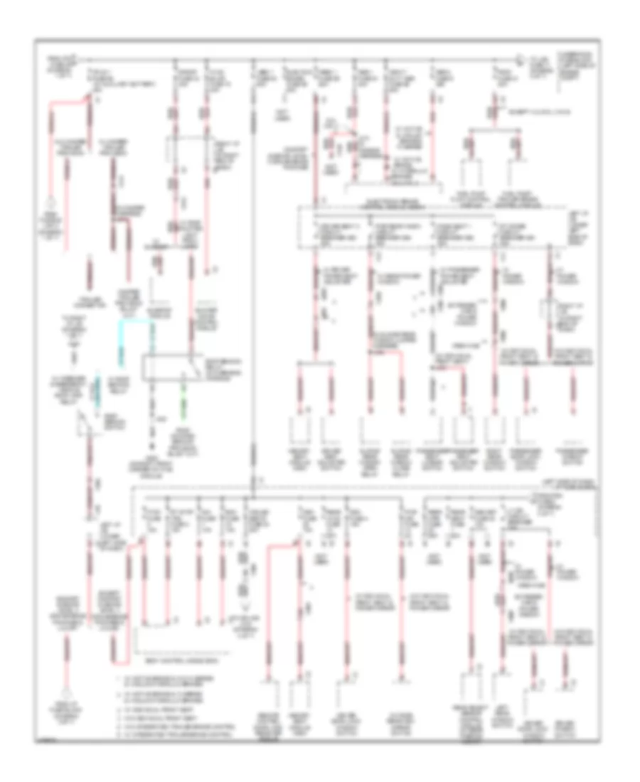
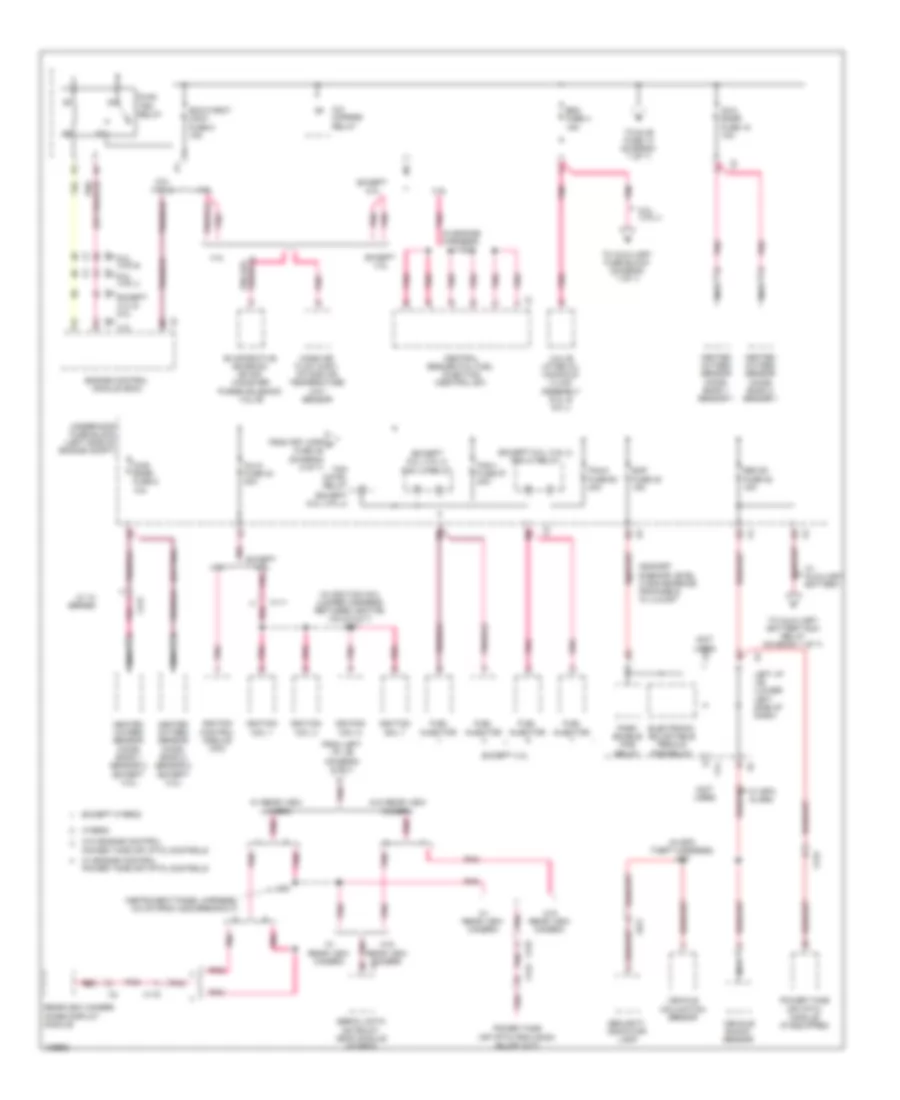
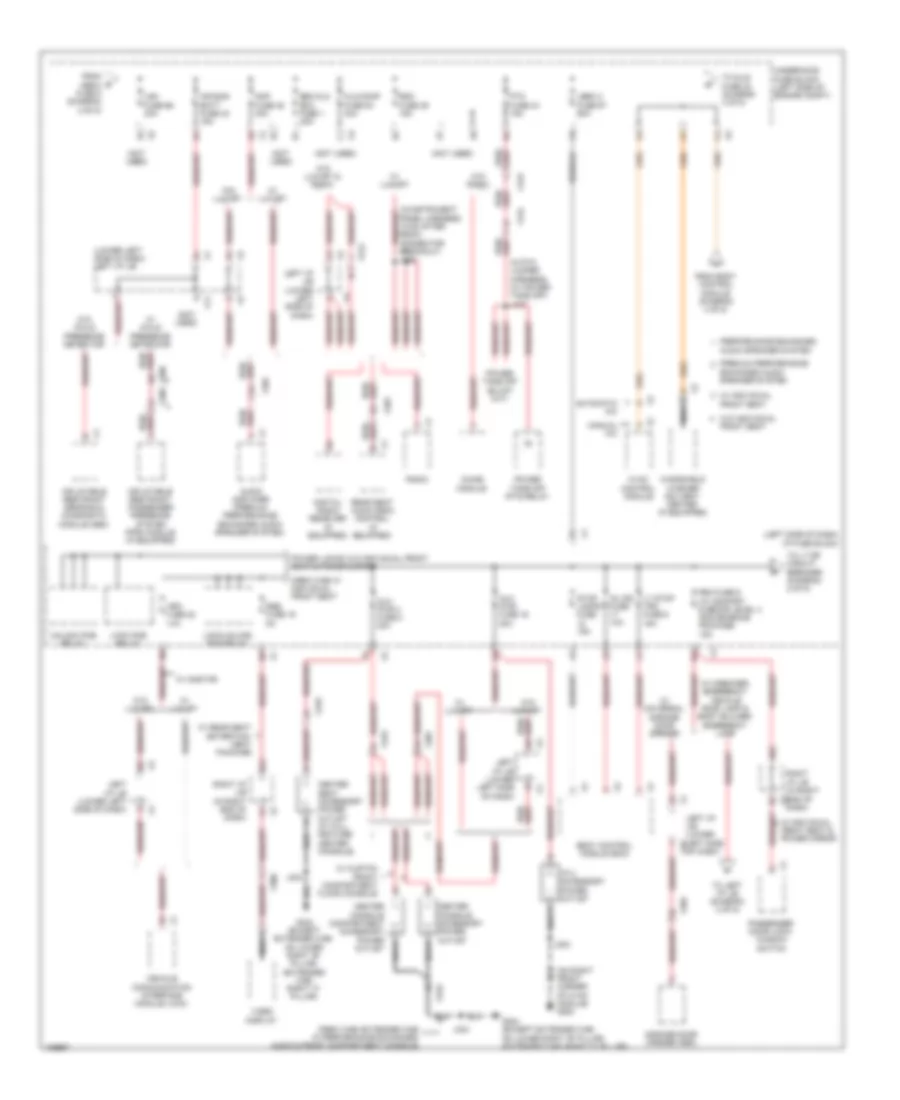
6.0L VIN G, Power Distribution Wiring Diagram (1 of 7) for Chevrolet Silverado 3500 HD LT 2013

List of elements for 6.0L VIN G, Power Distribution Wiring Diagram (1 of 7) for Chevrolet Silverado 3500 HD LT 2013:
- (4.3l:
- (except
- (in fuse block jumper harness) j210
- (in fuse block jumper harness) j211
- (in fuse block jumper harness) j224
- (in roof console) emergency vehicle roof lamp relay
- (not used)
- (on lower left front of engine) (except 4.3l) g102
- 125a
- 175a
- 2b5
- 4 speed a/t
- 4.3l: top rear of engine)
- 6 speed a/t
- 6.0l (vin g)
- 6.0l (vin j)
- 60a
- Automatic a/c
- Automatic transmission
- Auxiliary battery relay (if equipped) (rear of engine compt)
- Auxiliary battery run relay
- Body builder emergency lamp
- Body control module (bcm)
- Dash)
- Data link connector (dlc)
- Ecm- batt fuse 12 10a
- Engine control module (ecm)
- Evaporative emission (evap) canister vent solenoid valve
- Except 6.0l (vin j)
- From roof beacon switch (diagram 2 of 7)
- From underhood fuse block (diagram 3 of 7)
- From underhood fuse block (diagram 6 of 7)
- Fuse a 30a
- Fuse b 30a
- Fuse c 30a
- Fuse d 30a
- G103
- G107 (4.3l) (top left rear of engine)
- G200 (on right front corner of hvac module)
- Generator
- Ground distribution system
- Hdlp wash fuse 22 20a
- Heated seat control module (if equipped)
- Hvac batt fuse 39 10a
- Hvac control module
- I/p 1 accessory power outlet
- Instrument panel cluster (ipc)
- Ipc fuse 46 10a
- Itbc fuse 6 15a
- J145
- J200
- J209 (in fuse block jumper harness)
- J219
- Left battery
- Left i/p j/b (lower left x2 side of dash)
- Ltr fuse 53 20a
- Manual a/c
- On front of right cylinder head)
- Red
- Relay a
- Relay b
- Right battery
- Right i/p j/b (in right end of x2
- Seo b2 fuse 37 30a
- Starter motor
- Stud 2 fuse 63 30a
- Tcm-batt fuse 14 15a
- To auxiliary fuse block (diagram 7 of 7)
- To left i/p j/b (diagram 4 of 7)
- To stud 1 fuse 68 (diagram 2 of 7)
- To underhood fuse block (diagram 2 of 7)
- Trailer brake control module (if equipped)
- Trailer brake controller solid state relay
- Transfer case encoder motor
- Transfer case shift control module
- Transmission control module (tcm)
- Trec fuse 67 30a
- Underhood fuse block (left side of engine compt)
- Underhood fuse holder (on positive battery terminal)
- W/ active 2 speed
- W/ auxiliary battery
- W/ electronic 2 speed & active 2 speed
- W/ emergency vehicle roof lamp relay
- W/ wrecker emergency lamp provisions
- W/ wrecker relay
- Wrecker relay
- Wsw/htr fuse 66 60a
- X109
- X116
- X121
- X122
- X14
- X205
- X214
- X224
- X225
- X226
- X228
- X313
- X331
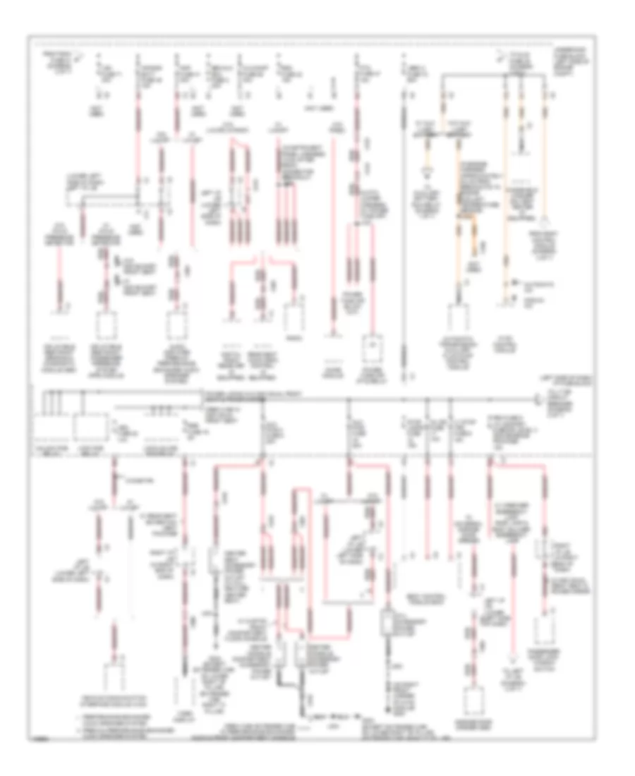
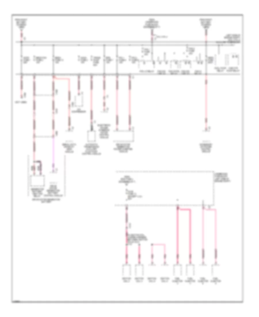
6.0L VIN G, Power Distribution Wiring Diagram (2 of 7) for Chevrolet Silverado 3500 HD LT 2013
List of elements for 6.0L VIN G, Power Distribution Wiring Diagram (2 of 7) for Chevrolet Silverado 3500 HD LT 2013:
- & vacuum/hydraulic brakes
- (in camper harness) j414
- (in sliding rear window jumper harness) j336
- (left side of dash) i/p fuse block
- (not used)
- (w/ individual front seat) j315
- 2b1
- 3b4
- 6.0l (vin j)
- Abs-1 fuse 61 40a
- Abs-2 fuse 9 25a
- Bcm fuse 10a
- Blower motor control module
- Body control modue (bcm)
- Comfort & decor level 3 convenience package
- Comfort & decor level 3 convenience package & luxury
- Cooled seats fuse 24 20a
- Crew cab
- Ctsy fuse 15a
- Ddm fuse 4 15a
- Dim fuse 10a
- Driver door lock/ window switch
- Driver seat 2 circuit breaker cb3 25a
- Driver seat adjuster switch
- Driver window switch
- Dsm fuse 10a
- Elec run board fuse 65 30a
- Electronic brake control module (ebcm)
- Except 4.3l/6.0l (vin g)
- Except comfort & decor level 3 convenience package & luxury
- Extended cab & power window
- From fusible link 3 (diagram 1 of 7)
- From i/p fuse block (diagram 3 of 7)
- From ipc f fuse 46 (diagram 1 of 7)
- From pdm fuse 9 (diagram 3 of 7)
- Fscm fuse 21 20a
- Fuel pump flow control module
- Fuel pump/ trailer brake control module
- G200 (on right front corner of hvac module)
- Heavy duty abs fuse 59 60a
- Hvac blwr fuse 70 40a
- J313 (in chassis harness)
- J323
- Lbec 1 fuse 64 60a
- Left i/p j/b (lower left side of dash)
- Left i/p j/b (lower left side x1
- Left rear window switch
- Lt dr circuit breaker 25a
- Mbec 1 fuse 69 60a
- Memory seat module (msm)
- Obs det fuse 20 10a
- Of dash)
- Outside rearview mirror switch
- Pass seat 1 circuit breaker cb2 25a
- Passenger door lock/ window switch
- Passenger seat adjuster switch
- Passenger seat lumbar switch
- Passenger window switch
- Pwr mir fuse 2a
- Pwr rear wndw circuit breaker cb4 25a
- Rear hvac fuse 30a
- Rear object sensor control module (w/ rear parking assist)
- Rear seat fuse 20a
- Rear wpr fuse 25a
- Red
- Remote control door lock receiver (rcdlr)
- Right i/p j/b (in right end of dash) x6
- Right i/p j/b (in right end of x3 dash)
- Right rear window switch
- Roof beacon relay (in overhead console)
- Roof beacon switch
- Rt doors circuit breaker cb1 25a
- Rt stop trn fuse 8 15a
- S/roof fuse 34 30a
- Sliding rear window close relay
- Sliding rear window open relay
- Stud 1 fuse 68 (w/ auxiliary battery) 40a
- Sunroof module
- To lgm fuse 71 (diagram 3 of 7)
- To right i/p j/b (diagram 1 of 7)
- To splice j318 (diagram 4 of 7)
- Trailer connector
- Underhood fuse block (left side of engine compt)
- W/ active & vacuum brake & 10 series
- W/ active brake
- W/ active brake & 10 series
- W/ active brake & w/o 10 series
- W/ camper trailer provision
- W/ driver power seat adjuster
- W/ hydraulic brakes 6.0l (vin j)
- W/ individual front seat
- W/ individual front seat & power mirror
- W/ integrated trailer brake control
- W/ passenger power seat adjuster
- W/ power window
- W/ rear power window
- W/ roof beacon relay
- W/ roof mounted light provi- lions
- W/ sunroof
- W/ wrecker & emergency vehicle roof lamp relay
- W/o camper trailer provision
- W/o individual front seat
- W/o individual front seat & power mirror
- W/o integrated trailer brake control
- X10
- X11
- X12
- X129
- X303
- X304
- X305
- X313
- X320
- X414
- X700
- X800
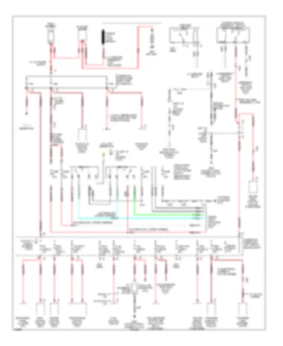
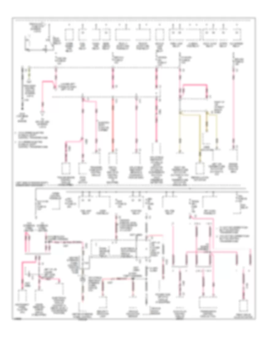
6.0L VIN G, Power Distribution Wiring Diagram (3 of 7) for Chevrolet Silverado 3500 HD LT 2013
List of elements for 6.0L VIN G, Power Distribution Wiring Diagram (3 of 7) for Chevrolet Silverado 3500 HD LT 2013:
- (in pto jumper harness) (w/ power take off) j127
- (left side of dash) i/p fuse block
- (lower left side of dash) left i/p j/b
- (not used)
- (on right front corner of hvac module) g200
- 2a1
- 3b2
- Air bag batt fuse 45 15a
- Alc/comp fuse 58 40a
- Amp fuse 41 30a
- Audio amplifier (premium performance enhanced audio speaker system)
- Audio speaker system
- Automatic a/c
- Automatic transmission auxiliary fluid pump control module
- Aux pwr 2 fuse 2 20a
- Aux pwr fuse 20a
- B1 x4
- Body control module (bcm)
- Center console accessory power outlet
- Center seat accessory power outlet (w/ full feature center seat)
- Chime module
- Crew cab w/ individual front seat
- Crew cab/ extended cab w/ performance exhanced audio & front compartment console
- Dash)
- Digital radio receiver (if equipped)
- Esc/alc exh fuse 2 30a
- From body control module (diagram 4 of 7)
- From fscm fuse 21 (diagram 2 of 7)
- G304 (except extended cab: on lower right "b" pillar) (extended cab: right "c" pillar)
- Garage door opener (gdo)
- Hvac control module
- I/p 2 accessory power outlet
- Inflatable restraint passenger presence system (pps) module
- Inflatable restraint sensing & diagnostic module (sdm)
- Info fuse 22 10a
- Is lps fuse 10a
- J203
- J304
- Lbec 2 fuse 72 60a
- Left i/p j/b (lower left side of dash)
- Left i/p j/b (lower left side x10
- Lgm fuse 71 30a
- Lock pcb relay
- Lock/unlock pcb relay
- Lt stop trn fuse 6 15a
- Manual a/c
- Nca
- Of dash)
- Passenger door lock/ window switch
- Pdm fuse 9 (w/ comfort & decor level 3 convenience package) 15a
- Performance enhanced
- Power locks w/o individual front seat & power mirror
- Power take off (pto) relay
- Premium performance enhanced
- Pto fuse 47 15a
- Radio
- Rdo fuse 42 15a
- Rear seat audio (rsa) control (if equipped)
- Red/
- Right i/p j/b (in right end of dash)
- Right i/p j/b (in right end of x3
- Rse fuse 19 5a
- Stop lamps fuse 15a
- T0 auxiliary battery run relay (diagram 1 of 7)
- To dlis fuse 35 (diagram 4 of 7)
- To left i/p j/b (diagram 2 of 7)
- To lt dr circuit breaker (diagram 2 of 7)
- Underhood fuse block (left side of engine compt)
- Unlock pcb relay
- Vehicle communication interface module (vcim)
- Video display
- W/ aux- iliary battery
- W/ child presence detector
- W/ custom front compartment floor console
- W/ individual front seat & power mirror
- W/ luxury
- W/ non bucket front seat
- W/ rear seat entertain- ment package
- W/ universal garage door opener
- W/ wrecker emergency lamp, roof lamp & body builder emergency lamp
- W/o aux- iliary battery
- W/o child presence detector
- W/o luxury
- W/o luxury & radio
- W/o non bucket front seat
- W/o radio
- W/onstar
- Windshield washer solvent heater (if equipped)
- X11
- X123
- X124
- X150
- X212
- X301
- X304
- X305
- X306
- X319
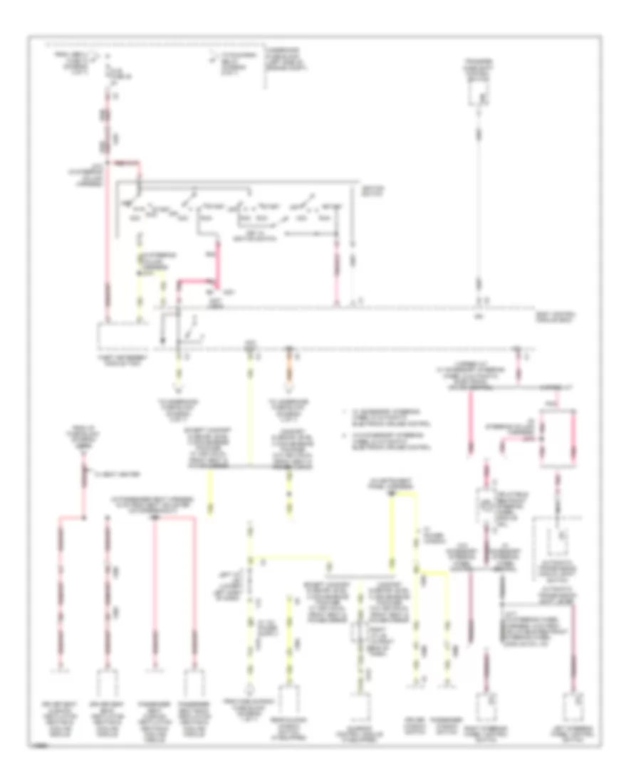
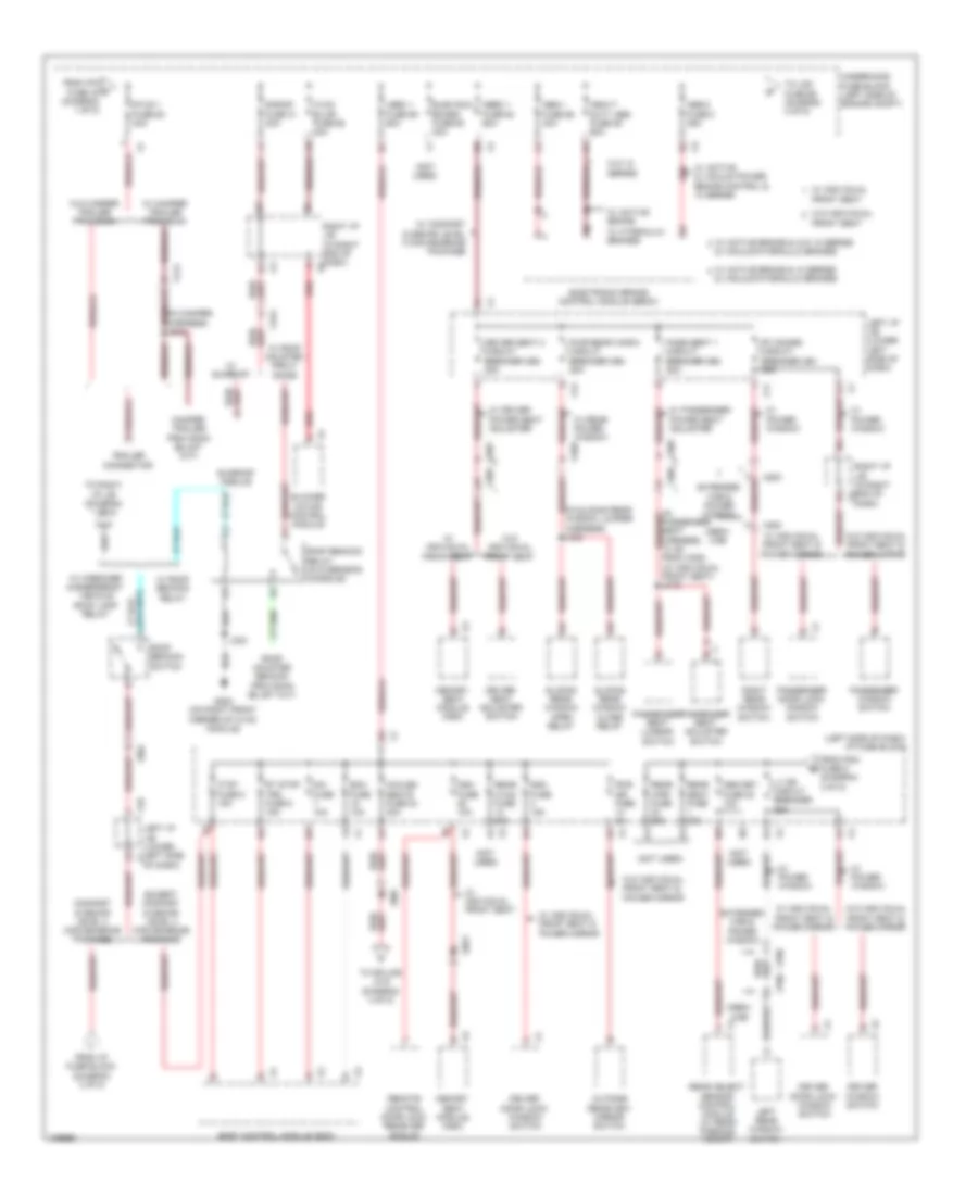
6.0L VIN G, Power Distribution Wiring Diagram (4 of 7) for Chevrolet Silverado 3500 HD LT 2013
List of elements for 6.0L VIN G, Power Distribution Wiring Diagram (4 of 7) for Chevrolet Silverado 3500 HD LT 2013:
- (in instrument panel harness) j231
- (in passenger seat harness, 15 cm from seat adjuster motor breakout) j318
- (in steering column harness) j216
- (not used)
- 12v
- 2b3
- 4 speed a/t w/ accessory steering wheel & automatic electronic cruise control
- 6 speed a/t
- Acc
- Acc volt
- Automatic transmission manual shift switch
- Automatic transmission shift lever
- Body control module (bcm)
- Column harness) j213
- Comfort & decor level 3 convenience package w/o individual front seat & power mirror
- Dash)
- Dlis fuse 35 2a
- Driver seat back ventilation heating & cooling module
- Driver seat cushion ventilation heating & cooling module
- Driver window switch
- Except comfort & decor level 3 convenience package w/ individual front seat & power mirror
- From i/p fuse block (diagram 2 of 7)
- From lbec 2 fuse 72 (diagram 3 of 7)
- From mobile radio fuse block (diagram 1 of 7)
- Ign
- Ignition switch
- Inflatable restraint steering wheel module coil
- J212 (in steering column harness)
- Key in ignition switch
- Left i/p j/b (lower left side of dash)
- Left steering wheel control switch
- Nca
- Off
- Passenger seat back ventilation heating & cooling module
- Passenger seat cushion ventilation heating & cooling module
- Passenger window switch
- Pnk
- Rear sliding window switch (if equipped)
- Right i/p j/b (in right end of x2
- Right steering wheel control switch
- Run
- Start
- Sunroof control module (if equipped)
- Theft deterrent module (tdm)
- To run/crnk relay (diagram 5 of 7)
- To underhood fuse block (diagram 3 of 7)
- To underhood fuse block (diagram 5 of 7)
- Transfer case shift control switch
- Underhood fuse block (left side of engine compt)
- W/ accessory steering wheel & automatic electronic cruise control
- W/ accessory steering wheel control
- W/ power window
- W/ seat heater
- W/o accessory steering wheel & automatic electronic cruise control
- W/o accessory steering wheel control
- X14
- X201
- X202
- X219
- X303
- X304
- X305
- X313
- X500
- X600
6.0L VIN G, Power Distribution Wiring Diagram (5 of 7) for Chevrolet Silverado 3500 HD LT 2013
List of elements for 6.0L VIN G, Power Distribution Wiring Diagram (5 of 7) for Chevrolet Silverado 3500 HD LT 2013:
- (in chassis harness) (6.0l (vin j)) j301
- (in engine harness) j130
- (in fuse block jumper harness) j220
- (not used)
- 4 speed a/t
- 6 speed a/t
- 6.0l (vin j)
- 7.5a
- A/c cmprsr relay
- Air bag ign fuse 40 10a
- Automatic transmission (4 speed a/t)
- Automatic transmission (6 speed a/t & 2 mode hybrid)
- Aux hvac- ign fuse 48 10a
- Bck/up lamp pcb relay
- Chmsl pcb relay
- Digital video disc (dvd) control module (if equipped)
- Drive motor generator power inverter module (6.0l (vin j))
- Drl pcb relay
- Ecm-ign fuse 56 15a
- Electric shift & active 2 speed
- Electronic brake control module (ebcm)
- Electronic compass module (comfort & decor level 3 convenience package)
- Engine control module (ecm)
- Equipped)
- Except 4.3l & 6.0l (vin g)
- Fog lamp relay
- From body control module (diagram 4 of 7)
- From dlis fuse 35 (diagram 4 of 7)
- Front drive axle actuator
- Frt wash pcb relay
- Frt wpr fuse 36 25a
- Fuel pmp relay
- Fuel pump flow control module
- Fuel pump/ trailer brake control module (if equipped)
- G107 (4.3l) g102 (except 4.3l) (4.3l: top left rear of engine) (except 4.3l: on lower left front of engine)
- Hdlp lo/hid relay
- Heated steering wheel control module
- Heated steering wheel control module inline fuse
- Hi beam pcb relay
- Horn pcb relay
- Hvac-ign fuse 55 10a
- Inflatable restraint i/p module on/off indicator (w/ manual suspression switch & child presence detector)
- Inflatable restraint sensing & diagnostic module (sdm)
- Inflatable restraint steering wheel module coil
- Inside rearview mirror (isrvm) (if equipped)
- Instrument panel cluster (ipc)
- J105
- Left air temperature actuator (automatic a/c)
- Left i/p j/b (lower left side of dash)
- Misc ign fuse 43 10a
- Mode actuator
- Nca
- Park lamp relay
- Pnk
- Rear defog relay
- Recirculation actuator
- Red
- Right air temperature actuator (automatic a/c) air temperature actuator (manual a/c)
- Right i/p j/b (in right end of dash)
- Run/ crnk relay
- Secondary fuel pump relay (6.0l (vin g) w/o auxiliary (fscm) fuel tank)
- Seo/alc fuse 54 10a
- Stop lamp switch
- Strtr relay
- To fan-1 fuse 57 (diagram 6 of 7)
- To splice j280 (diagram 6 of 7)
- Trans ign 1 fuse 19 15a
- Transfer case shift control module (if
- Transmission control module (tcm)
- Trlr lt stop/turn pcb relay
- Trlr rt stop/turn pcb relay
- Underhood fuse block (left side of engine compt)
- W/ 2 speed electric shift control transfer case
- W/ 2 speed manual shift control transfer case & active 2 speed push button control transfer case
- W/ active 2 speed push button control transfer case
- W/ steering wheel heater
- W/o 2 speed electric shift control transfer case
- W/o 2 speed manual shift control transfer case & active 2 speed push button control transfer case
- W/o active 2 speed push button control transfer case
- W/o steering wheel heater
- Wiper control pcb relay
- Wiper speed pcb relay
- X102
- X11
- X110
- X14
- X175
- X201
- X205
- X276
- X304
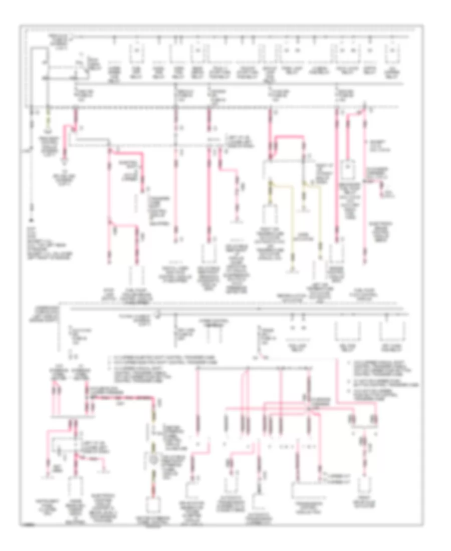
6.0L VIN G, Power Distribution Wiring Diagram (6 of 7) for Chevrolet Silverado 3500 HD LT 2013
List of elements for 6.0L VIN G, Power Distribution Wiring Diagram (6 of 7) for Chevrolet Silverado 3500 HD LT 2013:
- (except 6.0l (vin j))
- (except 6.0l (vin j)) fan hi relay
- (except 6.0l (vin j)) fan lo relay
- (in ignition coil jumper harness, between ignition coils 5 & 7) j107
- (in spo theft harness) j227
- (instrument panel harness, 6.5 cm from x205 breakout)
- (not used)
- (or pnk)
- 4.3l
- 6.0l (vin g)
- 6.0l (vin j)
- A/c cmprsr relay
- Central sequential fuel injection (central sfi)
- Comfort & decor level 3 convenience package & w/ luxury
- Eap fuse 38 15a
- Ecm/throt cont fuse 5 15a
- Electronic adjustable pedals pcb relay
- Eng fuse 4 15a
- Engine control module (ecm)
- Evaporative emission (evap) canister purge solenoid valve
- Except 4.3l
- Except 4.3l & 6.0l
- Except hybrid
- Fan cntrl relay
- Fan-1 fuse 57 40a
- Fan-2 fuse 60 40a
- From frt wpr p fuse 36 (diagram 5 of 7)
- From left i/p j/b (diagram 5 of 7)
- Fuel injector
- H pnk
- Heated oxygen sensor (ho2s) bank 1 sensor 1
- Heated oxygen sensor (ho2s) bank 1 sensor 2 (except 4.3l)
- Heated oxygen sensor (ho2s) bank 2 sensor 1
- Heated oxygen sensor (ho2s) bank 2 sensor 2 (except 4.3l)
- Hybrid
- Ignition coil 1
- Ignition coil 3
- Ignition coil 5
- Ignition coil 7
- Ignition control module (icm)
- Inj-a fuse 24 20a
- J128
- J280
- Mass air flow (maf)/ intake air temperature (iat) sensor
- Nca
- O2-a snsr fuse 18 10a
- O2-b snsr fuse 8 10a
- Park enable pcb relay
- Pnk
- Pnk (in engine harness)
- Power take off (pto) module (if equipped)
- Pwr/ trn relay
- Rearview camera image display module
- Red
- Security indicator lamp
- Seo b1 fuse 52 15a
- Serial data gateway (sdg) module (hybrid)
- To auxiliary battery run relay (diagram 1 of 7)
- To auxiliary fuse block (diagram 7 of 7)
- To inj-b fuse 13 (diagram 7 of 7)
- Underhood fuse block (left side of engine compt)
- Valve lifter oil manifold (vlom) assembly (5.3l & 6.0 l)
- Vehicle inclination sensor
- Vehicle shock sensor
- W/ 10 series
- W/ auxiliary battery
- W/ engine control power take off (pto) controls
- W/ rear view camera
- W/ spo alarm
- W/o engine control power take off (pto) controls
- W/o rear view camera
- X111
- X115
- X123
- X124
- X131
- X14
- X2 left i/p j/b (lower left side of dash)
- X227
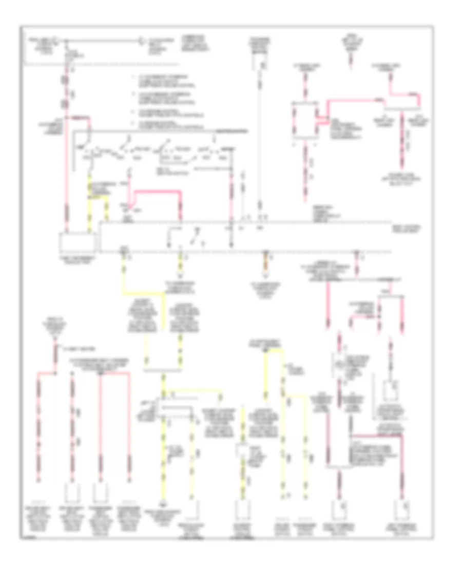
6.0L VIN G, Power Distribution Wiring Diagram (7 of 7) for Chevrolet Silverado 3500 HD LT 2013
List of elements for 6.0L VIN G, Power Distribution Wiring Diagram (7 of 7) for Chevrolet Silverado 3500 HD LT 2013:
- (left side of engine compt) (6.0l (vin j)) auxiliary fuse block
- (not used)
- 6.0l (vin j)
- A/c compressor
- Accessory dc power control module
- Accm fuse 3 15a
- Acpo fuse 1 25a
- Automatic transmission auxiliary fluid pump control module
- Becm fan fuse 2 15a
- Becm fuse 10 15a
- Cab htr pump relay
- Cool pump relay
- Drive motor generator battery
- Drive motor generator battery control module
- Drive motor generator power inverter module
- Electronic power steering motor control module
- Eps fuse 7 15a
- Fan 1 fuse 40a
- Fan 2 fuse 40a
- Fan cntrl relay
- Fan hi relay
- Fan lo relay
- Fan mid 1 relay
- Fan mid 2 relay
- From eng fuse 4 (diagram 6 of 7)
- From right battery (diagram 1 of 7)
- From underhood fuse block (diagram 6 of 7)
- Fuel injector
- Generator battery vent fan relay
- Ignition coil 2
- Ignition coil 4
- Ignition coil 6
- Ignition coil 8
- Inj-b fuse 13 (except 4.3l) 20a
- J395
- Mega fuse 200a
- Nca
- Pim 1 fuse 8 15a
- Pim 2 fuse 9 15a
- Pnk
- Pnk (in ignition coil jumper harness, between ignition coils 4 & 2) j110
- Red
- Serial data gateway (sdg) module
- Trans pump fuse 60a
- Underhood fuse block (left side of engine compt)
- X113
- X150
- X215
- X350
6.6L VIN 8
6.6L VIN 8, Power Distribution Wiring Diagram (1 of 5) for Chevrolet Silverado 3500 HD LT 2013
List of elements for 6.6L VIN 8, Power Distribution Wiring Diagram (1 of 5) for Chevrolet Silverado 3500 HD LT 2013:
- (in fuse block jumper harness) j210
- (in fuse block jumper harness) j211
- (in fuse block jumper harness) j224
- (in roof console) emergency vehicle roof lamp relay
- (not used)
- (top rear of engine) g103
- 125a
- 175a
- 2b5
- Automatic a/c
- Auxiliary generator
- Body builder emergency lamp
- Body control module (bcm)
- Data link connector (dlc)
- Ecm- batt fuse 11 10a
- Engine control module (ecm)
- From roof beacon switch (diagram 2 of 5)
- Fuse a 30a
- Fuse b 30a
- Fuse c 30a
- Fuse d 30a
- G200 (on right front corner of hvac module)
- Generator
- Glow plug control module (gpcm)
- Ground distribution system
- Hdlp wash fuse 20 20a
- Heated seat control module (if equipped)
- Hvac batt fuse 36 10a
- Hvac control module
- I/p 1 accessory power outlet
- Instrument panel cluster (ipc)
- Intake air heater (iah)
- Ipc fuse 43 10a
- Itbc fuse 19 15a
- J200
- J219
- Left battery
- Left i/p j/b (lower left side of dash)
- Ltr fuse 50 20a
- Manual a/c
- Red
- Relay a
- Relay b
- Right battery
- Right i/p j/b (in right end of x2 dash)
- Seo b2 fuse 34 30a
- Starter motor
- Stud 2 fuse 58 30a
- Tcm-batt fuse 7 15a
- To left i/p j/b (diagram 4 of 5)
- To stud 1 fuse 63 (diagram 2 of 5)
- Trailer brake control module (if equipped)
- Trailer brake controller solid state relay (if equipped)
- Transfer case encoder motor
- Transfer case shift control module
- Transmission control module (tcm)
- Trec fuse 62 30a
- Underhood fuse block (left side of engine compt)
- Underhood fuse holder (right side of firewall)
- W/ active 2 speed
- W/ dual generator & ambulance upfitter sales package
- W/ electronic 2 speed & active 2 speed
- W/ emergency vehicle roof lamp relay
- W/ wrecker emergency lamp provisions
- W/ wrecker relay
- Wrecker relay
- Wsw/htr fuse 61 60a
- X109
- X116
- X121
- X14
- X205
- X214
- X224
- X225
- X226
- X228
- X313
- X331
6.6L VIN 8, Power Distribution Wiring Diagram (2 of 5) for Chevrolet Silverado 3500 HD LT 2013
List of elements for 6.6L VIN 8, Power Distribution Wiring Diagram (2 of 5) for Chevrolet Silverado 3500 HD LT 2013:
- & vacuum/hydraulic brakes
- (in camper harness) j414
- (in sliding rear window jumper harness) j336
- (left side of dash) i/p fuse block
- (not used)
- 2b1
- 3b4
- Abs-1 fuse 56 40a
- Abs-2 fuse 8 25a
- Bcm fuse 10a
- Blower motor control module
- Body control module (bcm)
- Comfort & decor level 3 convenience package
- Cooled seats fuse 24 30a
- Crew cab
- Ctsy fuse 5 15a
- Dash)
- Ddm fuse 15a
- Dim fuse 10a
- Driver door lock/ window switch
- Driver seat 2 circuit breaker cb3 25a
- Driver seat adjuster switch
- Driver window switch
- Dsm fuse 10a
- Elec run board fuse 60 30a
- Electronic brake control module (ebcm)
- Except comfort & decor level 3 convenience package
- Extended cab & power window
- From i/p fuse block (diagram 3 of 5)
- From ipc c fuse 43 (diagram 1 of 5)
- From pdm fuse 9 (diagram 3 of 5)
- Front seat
- G200 (on right front corner of hvac module)
- Heavy duty abs fuse 55 60a
- Hvac blwr fuse 65 40a
- J323
- Lbec 1 fuse 59 60a
- Left i/p j/b (lower left side of dash)
- Left i/p j/b (lower left side x1
- Left rear window switch
- Lt dr circuit breaker 25a
- Mbec 1 fuse 64 60a
- Memory seat module (msm)
- Obs det fuse 20 10a
- Of dash)
- Outside rearview mirror switch
- Pass seat 1 circuit breaker cb2 25a
- Passenger door lock/ window switch
- Passenger seat adjuster switch
- Passenger seat harness, 10 cm from x305) (w/ individual front seat) j315
- Passenger seat lumbar switch
- Passenger window switch
- Pwr mir fuse 2a
- Pwr rear wndw circuit breaker cb4 25a
- Rear hvac fuse 30a
- Rear object sensor control module (w/ rear parking assist)
- Rear seat fuse 20a
- Rear wpr fuse 25a
- Red
- Remote control door lock receiver (rcdlr)
- Right i/p j/b (in right end of dash) x6
- Right i/p j/b (in right end of x3
- Right rear window switch
- Roof beacon relay (in overhead console)
- Roof beacon switch
- Rt doors circuit breaker cb1 25a
- Rt stop trn fuse 8 15a
- S/roof fuse 31 30a
- Sliding rear window close relay
- Sliding rear window open relay
- Stud 1 fuse 63 40a
- Sunroof module
- To lgm fuse 66 (diagram 3 of 5)
- To right i/p j/b (diagram 1 of 5)
- To splice j318 (diagram 4 of 5)
- Trailer connector
- Underhood fuse block (left side of engine compt)
- W/ active & vacuum power brake control & 10 series
- W/ active brake
- W/ active brake & 10 series
- W/ active brake & w/o 10 series & vacuum/hydraulic brakes
- W/ camper trailer provision
- W/ comfort & decor level 3 convenience package
- W/ driver power seat adjuster
- W/ hydraulic brakes
- W/ individual
- W/ individual front seat
- W/ individual front seat & power mirror
- W/ passenger power seat adjuster
- W/ power window
- W/ rear power window
- W/ roof beacon relay
- W/ roof mounted provi- sions
- W/ sunroof
- W/ wrecker & emergency vehicle roof lamp relay
- W/o 10 series
- W/o camper trailer provision
- W/o individual
- W/o individual front seat
- W/o individual front seat & power mirror
- X10
- X11
- X12
- X303
- X304
- X305
- X313
- X320
- X414
- X700
- X800
6.6L VIN 8, Power Distribution Wiring Diagram (3 of 5) for Chevrolet Silverado 3500 HD LT 2013
List of elements for 6.6L VIN 8, Power Distribution Wiring Diagram (3 of 5) for Chevrolet Silverado 3500 HD LT 2013:
- (in pto jumper harness) (w/ power take off) j127
- (left side of dash) i/p fuse block
- (lower left side of dash) left i/p j/b
- (not used)
- (on right front corner of hvac module) g200
- 2a1
- 3b2
- Air bag batt fuse 42 15a
- Alc/comp fuse 54 40a
- Amp fuse 38 30a
- Audio amplifier (premium performance enhanced audio speaker system)
- Audio speaker system
- Automatic a/c
- Aux pwr 2 fuse 2 20a
- Aux pwr fuse 16 20a
- Body control module (bcm)
- Center console accessory power outlet
- Center seat accessory power outlet (w/ full feature center console)
- Chime module
- Crew cab w/ individual front seat
- Crew cab/ extended cab w/ performance exhanced audio & front compartment console
- Dash)
- Digital radio receiver (if equipped)
- Enhanced audio speaker system
- Esc/alc exh fuse 1 30a
- From abs-2 fuse 8 (diagram 2 of 5)
- From body control module (diagram 4 of 5)
- Front seat
- G304 (except extended cab: on lower right "b" pillar) (extended cab: right "c" pillar)
- Garage door opener (gdo)
- Hvac control module
- I/p 2 accessory power outlet
- Inflatable restraint passenger presence system (pps) module (if equipped)
- Inflatable restraint sensing & diagnostic module (sdm)
- Info fuse 22 10a
- Is lps fuse 10a
- J203
- J304
- Lbec 2 fuse 67 60a
- Left i/p j/b (lower left side of dash)
- Left i/p j/b (lower left side x10
- Lgm fuse 66 30a
- Lock pcb relay
- Lock/unlock pcb relay
- Lt stop trn fuse 6 15a
- Manual a/c
- Nca
- Of dash)
- Passenger door lock/ window switch
- Pdm fuse 9 (w/ comfort & decor level 3 convenience package) 15a
- Performance enhanced
- Power locks w/o individual front seat & power mirror
- Power take off (pto) relay
- Premium performance
- Pto fuse 44 15a
- Radio
- Rdo fuse 39 15a
- Rear seat audio (rsa) control (if equipped)
- Right i/p j/b (in right end of dash)
- Right i/p j/b (in right end of x3
- Rse fuse 19 5a
- Stop lamps fuse 15a
- To dlis fuse 32 (diagram 4 of 5)
- To left i/p j/b (diagram 2 of 5)
- To lt dr circuit breaker (diagram 2 of 5)
- Underhood fuse block (left side of engine compt)
- Unlock pcb relay
- Vehicle communication interface module (vcim)
- Video display
- W/ child presence detector
- W/ custom front compartment floor console
- W/ individual
- W/ individual front seat & power mirror
- W/ luxury
- W/ onstar
- W/ rear seat entertain- ment package
- W/ universal garage door opener
- W/ wrecker, emergency vehicle roof lamp & body builder emergency lamp
- W/o child presence detector
- W/o individual
- W/o luxury
- W/o luxury & radio
- W/o radio
- Windshield washer solvent heater (if equipped)
- X11
- X123
- X124
- X212
- X301
- X304
- X305
- X306
- X319
6.6L VIN 8, Power Distribution Wiring Diagram (4 of 5) for Chevrolet Silverado 3500 HD LT 2013
List of elements for 6.6L VIN 8, Power Distribution Wiring Diagram (4 of 5) for Chevrolet Silverado 3500 HD LT 2013:
- (in instrument panel harness) j231
- (in passenger seat harness, 15 cm from seat adjuster motor breakout) j318
- (in steering column harness) j216
- (not used)
- 12v
- 2b3
- 4 speed a/t w/ accessory steering wheel & automatic electronic cruise control
- 6 speed a/t
- Acc
- Acc volt
- Automatic transmission manual shift switch
- Automatic transmission shift lever
- Body control module (bcm)
- Column harness) j213
- Comfort & decor level 3 convenience package w/o individual front seat & power mirror
- Dlis fuse 32 2a
- Driver seat back ventilation heating & cooling module
- Driver seat cushion ventilation heating & cooling module
- Driver window switch
- Except comfort & decor level 3 convenience package w/ individual front seat & power mirror
- From i/p fuse block (diagram 2 of 5)
- From lbec 2 fuse 67 (diagram 3 of 5)
- From left i/p j/b (diagram 5 of 5)
- From mobile radio fuse block (diagram 1 of 5)
- Ign
- Ignition switch
- Inflatable restraint steering wheel module coil
- J212 (in steering column harness)
- J280 (instrument panel harness, 6.5 cm from x205 breakout)
- Key in ignition switch
- Left i/p j/b (lower left side of dash)
- Left steering wheel control switch
- Nca
- Off
- Passenger seat back ventilation heating & cooling module
- Passenger seat cushion ventilation heating & cooling module
- Passenger window switch
- Pnk
- Rear sliding window switch (if equipped)
- Rearview camera image display module
- Red
- Right i/p j/b (in right end of x2 dash)
- Right steering wheel control switch
- Run
- Start
- Sunroof control module (if equipped)
- Theft deterrent module (tdm)
- To run/crnk relay (diagram 5 of 5)
- To underhood fuse block (diagram 3 of 5)
- To underhood fuse block (diagram 5 of 5)
- Transfer case shift control switch
- Underhood fuse block (left side of engine compt)
- W/ accessory steering wheel & automatic electronic cruise control
- W/ accessory steering wheel control
- W/ engine control power take off (pto) controls
- W/ power window
- W/ rear view camera
- W/ seat heater
- W/o accessory steering wheel & automatic electronic cruise control
- W/o accessory steering wheel control
- W/o engine control power take off (pto) controls
- W/o rear view camera
- X115
- X123
- X124
- X14
- X201
- X202
- X219
- X303
- X304
- X305
- X313
- X500
- X600
6.6L VIN 8, Power Distribution Wiring Diagram (5 of 5) for Chevrolet Silverado 3500 HD LT 2013
List of elements for 6.6L VIN 8, Power Distribution Wiring Diagram (5 of 5) for Chevrolet Silverado 3500 HD LT 2013:
- (in engine harness) j130
- (in fuse block jumper harness) j220
- (in spo theft harness) j227
- (left side of engine compt) underhood fuse block
- (lower left side of dash) left i/p j/b
- (not used)
- 7.5a
- A/c cmprsr relay
- Air bag ign fuse 37 10a
- Aux hvac- ign fuse 45 10a
- Bck/up lamp pcb relay
- Chmsl pcb relay
- Comfort & decor level 3 convenience package & w/ luxury
- Digital video disc (dvd) control module (if equipped)
- Drl pcb relay
- Eap fuse 35 15a
- Ecm-ign fuse 53 15a
- Electric shift & active 2 speed
- Electronic adjustable pedals pcb relay
- Electronic compass module (comfort & decor level 3 convenience package)
- Engine control module (ecm)
- Fan fuse 68 10a
- Fan relay
- Fog lamp relay
- From body control module (diagram 4 of 5)
- From dlis fuse 32 (diagram 4 of 5)
- Front drive axle actuator
- Frt wash pcb relay
- Frt wpr fuse 33 25a
- Fuel pmp relay
- G103 (top rear of engine)
- Glow plug control module (gpcm)
- Hdlp lo/hid relay
- Heated steering wheel control module
- Heated steering wheel control module inline fuse
- Hi beam pcb relay
- Horn pcb relay
- Hvac-ign fuse 52 10a
- Inflatable restraint i/p module on/off indicator (w/ manual suspression switch & child presence detector)
- Inflatable restraint sensing & diagnostic module (sdm)
- Inflatable restraint steering wheel module coil
- Inside rearview mirror (isrvm) (if equipped)
- Instrument panel cluster (ipc)
- J105
- Left air temperature actuator (automatic a/c)
- Left i/p j/b (lower left side of dash) x9
- Misc ign fuse 40 10a
- Mode actuator
- Nca
- Park enable pcb relay
- Park lamp relay
- Pnk
- Pnk c
- Power take off (pto) module (if equipped)
- Pwr/trn relay
- Rear defog relay
- Recirculation actuator
- Red
- Right air temperature actuator (automatic a/c) air temperature actuator (manual a/c)
- Right i/p j/b (in right end of dash)
- Run/ crnk relay
- Security indicator lamp
- Seo b1 fuse 15a
- Seo/alc fuse 51 10a
- Stop lamp switch
- Strtr relay
- To splice j280 (diagram 4 of 5)
- Trailer brake control module (if equipped)
- Trans ign 1 fuse 15a
- Transfer case shift control module
- Transmission control module (tcm)
- Trlr lt stop/turn pcb relay
- Trlr rt stop/turn pcb relay
- Vehicle inclination sensor
- Vehicle shock sensor
- W/ 2 speed electric & manual shift control transfer case
- W/ active 2 speed push button control transfer case
- W/ spo alarm
- W/ steering wheel heater
- W/o 2 speed electric & manual shift control transfer case
- W/o active 2 speed push button control transfer case
- W/o steering wheel heater
- Wiper control pcb relay
- Wiper speed pcb relay
- X102
- X107
- X11
- X110
- X123
- X14
- X2 left i/p j/b (lower left side of dash)
- X201
- X205
- X227
- X276
- X304