POWER DISTRIBUTION
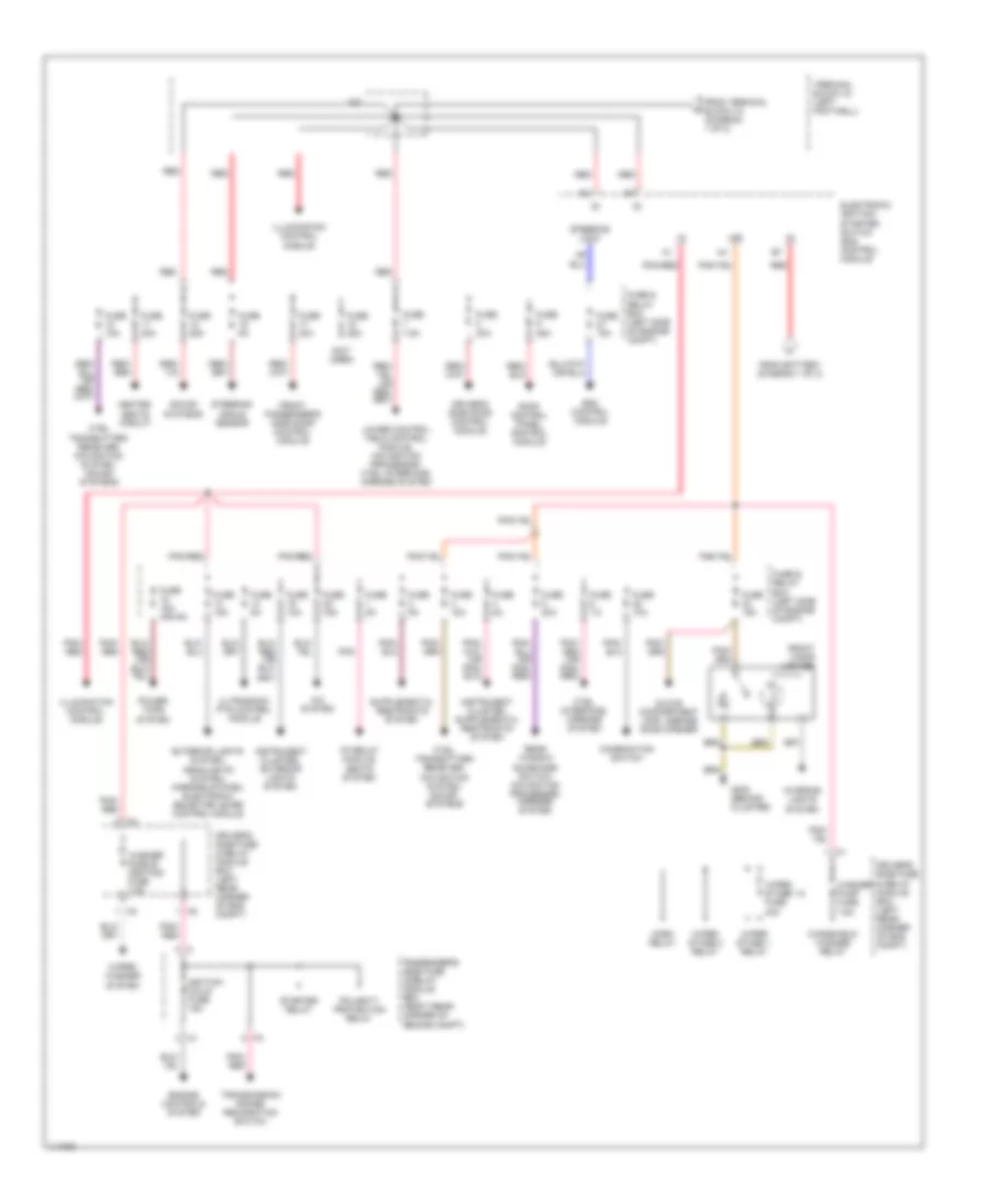
Power Distribution Wiring Diagram (1 of 2) for Mercedes-Benz CLK320 2000

List of elements for Power Distribution Wiring Diagram (1 of 2) for Mercedes-Benz CLK320 2000:
- 2.1
- 3.2
- A/c system
- Air pump relay module, asr/ets/esp hydraulic unit
- Battery
- Circuit 30z fuse 7.5a
- Control module box
- Data link connectors (obd ii, dtc readout)
- Driver's side fuse & relay module box (left rear of eng compt)
- Engine control module
- Esp/bas control module
- Fp relay module
- Fuse & relay box (left side of engine compt)
- Fuse 10a
- Fuse 15a
- Fuse 25a
- Fuse 30a
- Fuse 30a (or 60a)
- Fuse 40a
- Fuse 5a
- G405 (right side of luggage compartment)
- Generator, starter, esp/bas control module
- Hcs pump fuse 30a
- Hcs pump relay
- High pressure/ return pump relay
- Horn relay
- Horns fuse 10a
- Instrument cluster
- Interior lights system passenger's side door control module
- Interior lights system, anti- theft system
- Nca
- Oil cooler fan relay
- Passenger's side fuse & relay module box (right rear corner of engine compt)
- Polarity protection relay
- Power tops system
- Pse control module
- Rear fuse box
- Red
- Red/ pnk
- Reserve fuse 30a
- Sam fuse 15a
- Seats system
- Signal pick-up & activation module
- Starter
- Steering angle sensor
- Terminal block x12/3 (left rear of engine compt)
- Terminal block x4 (left footwell)
- To electronic ignition- starter switch control module (diagram 2 of 2)
- To terminal block x4 (diagram 2 of 2)
- W/ cabriolet
Power Distribution Wiring Diagram (2 of 2) for Mercedes-Benz CLK320 2000
List of elements for Power Distribution Wiring Diagram (2 of 2) for Mercedes-Benz CLK320 2000:
- (not used)
- 15r
- 2.2
- A/c system
- Cf relay module, seats system
- Combination switch
- Ctel interface, mirrors system
- Ctel transmitter/ receiver, navigation system, sound systems
- Driver's side door control module
- Driver's side fuse & relay module box (left rear corner of eng compt)
- Electronic ignition- starter switch (eis) control module
- Engine controls system
- Esc control module
- Exterior lights system, headlights system, mirrors system, electronic selector lever control module
- From battery (diagram 1 of 2)
- From terminal block x4 (diagram 1 of 2)
- Front cigar lighter
- Front passenger's side door control module
- Fuse & relay box (left side of engine compt)
- Fuse 10a
- Fuse 15a
- Fuse 15a (or 5a)
- Fuse 20a
- Fuse 25a
- Fuse 2o 15a
- Fuse 30a
- Fuse 5a
- Fuse 7.5
- Fuse 7.5a
- G202 (behind cluster)
- Glove compartment lamp, garage door opener
- Heated seats circuit
- Horn relay
- Ignition coils fuse 15a
- Illumination control module
- Instrument cluster, exterior lights system
- Interior lights system
- Lower control field control module, navigation processor, ctel interface, mirrors system
- Passenger's side fuse & relay module box (right rear corner of engine compt)
- Pnk
- Pnk/ red
- Pnk/red
- Polarity protection relay
- Power tops system
- Rear window sunshade switch, navigation processor, mirrors system
- Red
- Roof control panel control module
- Sound systems
- Starter relay
- Steering angle sensor
- Steering lock
- Terminal block x4 (left footwell)
- Transmission range recognition switch
- Ultrasonic pts control module
- Washer nozzle heating fuse 7.5a
- Washer pump fuse 7.5a
- Windshield washer relay
- Wiper stage 1 relay
- Wiper stage 1-2 fuse 40a
- Wiper stage 2 relay
- Wiper/ washer system