POWER DISTRIBUTION
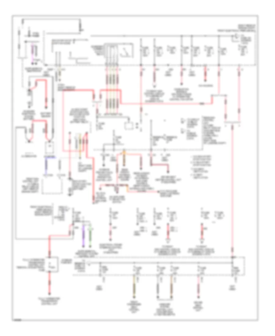
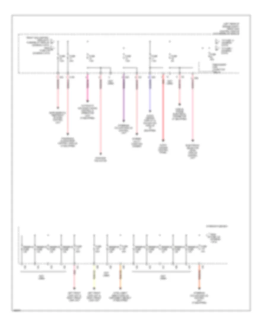
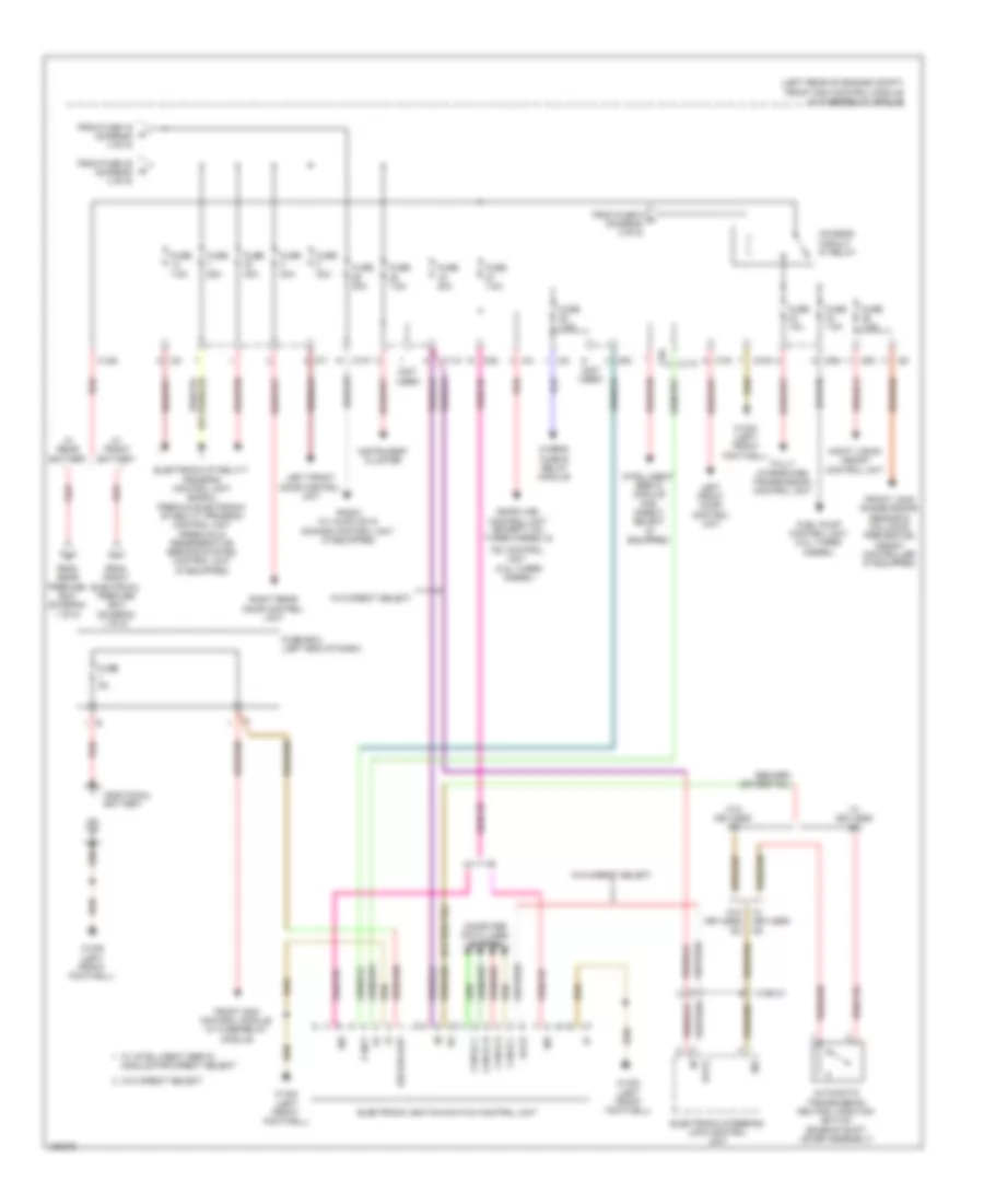
Power Distribution Wiring Diagram, Convertible (1 of 6) for Mercedes-Benz E350 4Matic 2014

List of elements for Power Distribution Wiring Diagram, Convertible (1 of 6) for Mercedes-Benz E350 4Matic 2014:
- (not used)
- (right rear of engine compt) front electrical prefuse box
- (w/ eco start stop function) eco start/stop function additional battery relay
- 200a 400a
- 60a
- A/c housing
- Airscarf system control unit (convertible w/ heated seats)
- Alternator
- Am amplifier w/ selection switch
- Am, fm & c2 (zv) antenna amplifier
- Battery sensor
- C116
- C117
- C123
- C124
- C126
- C127
- C18m
- C19i
- C3i
- C8d
- C9i
- Combustion engine & air conditioning w/ integrated control fan motor
- Driver seat control unit
- Driver seat heater control unit (if equipped)
- Eco start/ stop function additional battery
- Eco start/stop function diode
- Electrical power steering control unit (if equipped)
- From fuse a (diagram 1 of 6)
- Front electrical prefuse box (right rear of engine compt)
- Front passenger seat control unit
- Front sam control unit w/ fuse & relay module (left rear of engine compt)
- Fssp
- Fully integrated transmission control unit
- Fully integrated transmission control unit terminal 30 electrical fuse
- Fuse
- Fuse 100a
- Fuse 150a
- Fuse 200a
- Fuse 25a
- Fuse 30a
- Fuse 50a
- Fuse 50a 100a
- Fuse 60a
- Fuse 7.5a
- Fuse 80a
- Ig1
- Im1
- Interior fuse box
- Interior protection & tow-away protection control unit
- M10
- Mg1
- Mg2
- Mr1
- Mr2
- Mr3
- Mr4
- Mr5
- Mr7
- Mr8
- Mr9
- On board electrical system battery
- Pyro fuse
- Quiescent current cutout relay
- Rear sam control unit w/ fuse/ relay module (convertible: in spare wheelwell) (coupe: right side of luggage compt)
- Rear window antenna amplifier 1 (coupe)
- Rear window antenna fm antenna amplifier (coupe) & rear window antenna amplifier 2 (coupe)
- Red
- Res fuse
- Reserve fuse
- Reserve fuse 20a
- Starter
- Stop function
- To circuit 15 relay (diagram 2 of 6)
- To front sam control module w/ fuse/relay module (diagram 4 of 6)
- To front sam control module w/ fuse/relay module (diagram 6 of 6)
- To fuse 150 (diagram 1 of 6)
- To fuse 89 (diagram 2 of 6)
- To reserve fuse 118 (diagram 5 of 6)
- Tv3, fm2 & dab band 3 antenna amplifier
- W/ eco start/ stop function
- W/ seat ventilation
- W/o eco start/
- W/o seat ventilation
- W16/4 (right rear of engine compt)
- W7 (right side of luggage compt)
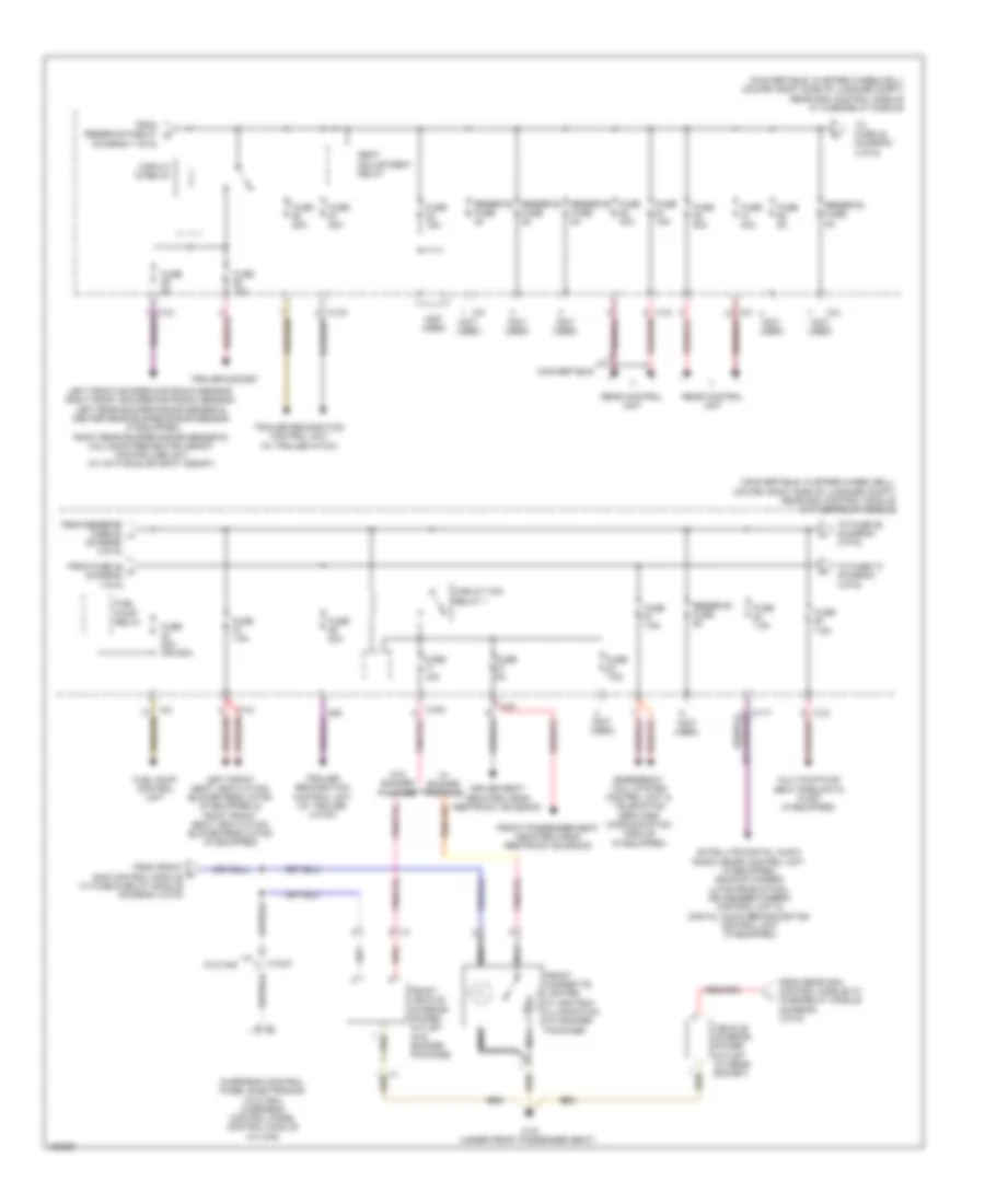
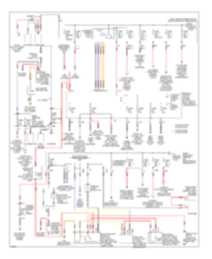
Power Distribution Wiring Diagram, Convertible (2 of 6) for Mercedes-Benz E350 4Matic 2014
List of elements for Power Distribution Wiring Diagram, Convertible (2 of 6) for Mercedes-Benz E350 4Matic 2014:
- (convertible: in spare wheelwell) (coupe: right side of luggage compt) rear sam control module w/ fuse/relay module
- (diagram 1 of 6)
- (not used)
- 13a
- C11t
- C12i
- C13a
- C14i
- C15h
- C3i
- C89
- Circuit 15 relay
- Circuit 15r relay 1
- Convertible
- Driver seat neck-pro head restraint solenoid
- Emergency call system control unit & telematics services communication module (if equipped)
- From front m sam control module w/ fuse & relay module (diagram 4 of 6)
- From fuse 46 c (diagram 1 0f 6)
- From rear sam control module w/ fuse/relay module (diagram 3 0f 6)
- From reserve fuse 47 d
- From reserve fuse 52 h (diagram 2 0f 6)
- Front cigarette lighter w/ ashtray illumination (w/ smoker package)
- Front passenger seat neck-pro head restraint solenoid
- Front vehicle interior power outlet (w/o smoker package)
- Fuel pump control unit
- Fuel pump relay
- Fuse 15a
- Fuse 20a
- Fuse 20a (or 25a)
- Fuse 30a
- Fuse 40a
- Fuse 5a
- Fuse 7.5a
- Left front bumper distronic sensor, right front bumper distronic sensor, left rear bumper radar sensor & center rear bumper radar sensor (if equipped) right rear bumper radar sensor & collision prevention assist controller unit (w/ active blind spot assist)
- Left front seat ventilation blower regulator (if equipped) & right front seat ventilation blower regulator (if equipped)
- Multicontour seat pneumatic pump (if equipped)
- Nca
- Overhead control panel electronics (w/o can) overhead control panel control module (w/ can)
- Rear control unit
- Red
- Reserve fuse
- Satellite digital audio radio (sdar) control unit (if equipped), backup camera (late production), 360 degree camera control unit & digital audio broadcasting control unit (if equipped)
- Seat adjustment relay
- To fuse 42 (diagram 2 of 6)
- To fuse 73 (diagram 3 0f 6)
- To fuse 85 (diagram 3 0f 6)
- Trailer recognition control unit (w/ trailer hitch)
- Trailer socket
- Vehicle interior power outlet (w/ rear socket)
- W/ smoker package
- W/o can
- W/o smoker package
- W19 (under front passenger seat)
- X18/37
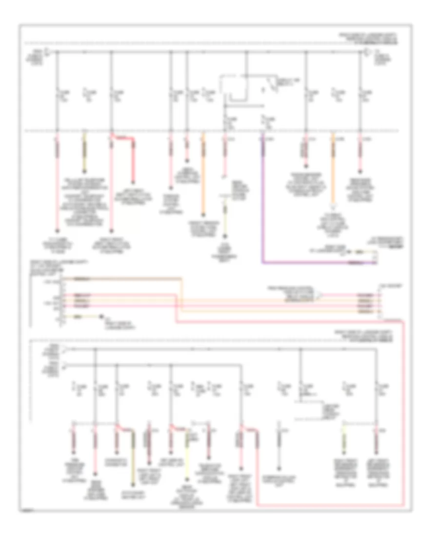
Power Distribution Wiring Diagram, Convertible (3 of 6) for Mercedes-Benz E350 4Matic 2014
List of elements for Power Distribution Wiring Diagram, Convertible (3 of 6) for Mercedes-Benz E350 4Matic 2014:
- (convertible)
- (convertible: in spare wheelwell) (coupe: right side of luggage compt) rear sam control module w/ fuse/relay module
- (coupe)
- (not used)
- (or pnk/red) red
- Adaptive damping system control unit (if equipped)
- C11r
- C11t
- C12i
- C14i
- C15h
- C2g
- C66
- Chassis gateway control unit
- Circuit 15r relay 2
- Compensator/cellular telephone system umts (w/ mobile phone preinstallation w/ universal interface & w/ stationary heater)
- Coolant circulation pump relay (4.6l twin turbo)
- Diagnostic connector
- From fuse 60 (diagram 2 of 6)
- From fuse 84 (diagram 2 0f 6)
- From reserve fuse 91 n (diagram 3 0f 6)
- Fuse 15a
- Fuse 20a
- Fuse 30a
- Fuse 40a 30a
- Fuse 50a
- Fuse 5a
- Fuse 7.5a
- Keyless go control unit (if equipped)
- Left front reversible emergency tensioning retractor (if equipped)
- Media interface control unit (w/ auxiliary jack)
- Parking system control unit (if equipped)
- Radar sensors control unit (if equipped)
- Rear window heated relay
- Red
- Reserve fuse
- Right front reversible emergency tensioning retractor (if equipped)
- Sound system amplifier control unit (if equipped)
- Stationary heater radio remote control receiver (if equipped)
- Stationary heater unit (if equipped)
- Tire pressure monitor control unit (if equipped)
- To fuse 70 (diagram 3 of 6)
- To vehicle interior power outlet (diagram 2 of 6)
- Tv tuner (analog/digital) (if equipped) & tv digital tuner (if equipped)
- Weight sensing system (wss) control unit (if equipped)
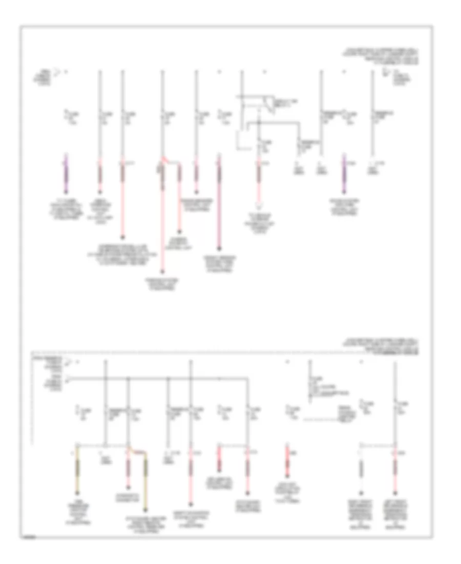
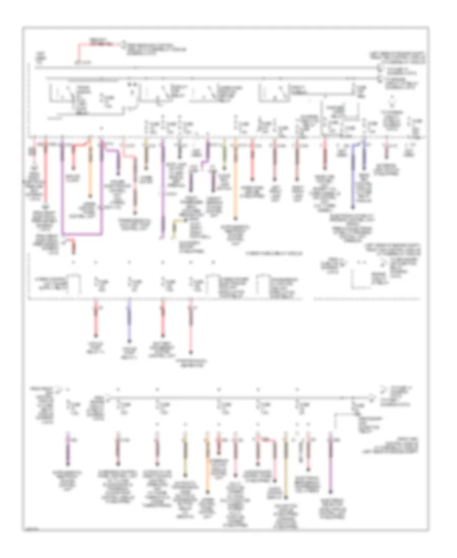
Power Distribution Wiring Diagram, Convertible (4 of 6) for Mercedes-Benz E350 4Matic 2014
List of elements for Power Distribution Wiring Diagram, Convertible (4 of 6) for Mercedes-Benz E350 4Matic 2014:
- (left rear of engine compt) front sam control module w/ fuse/relay module
- (not used)
- 16s
- 19i
- C11c
- C14m
- C15m
- C19i
- C1m
- C6i
- C7i
- Circuit 15 relay
- Circuit 15r relay
- Driver seat heater control unit (if equipped)
- Electronic stability program control unit (basic) premium electronic stability program control unit (premium)
- Engine circuit 87 relay
- Exterior light switch
- Fanfare horn relay
- From front electrical prefuse box (diagram 1 of 6)
- Front passenger seat occupied recognition & acsr (if equipped)
- Fuse 10a
- Fuse 15a
- Fuse 20a
- Fuse 30a
- Fuse 31a 15a
- Fuse 31b 15a
- Fuse 7.5a
- Glove box lamp switch
- Glove box socket (if equipped)
- Instrument panel switch group
- Left xenon lamp control unit (w/ xenon) left front lamp unit (w/o xenon)
- Me-sfi (me) control unit
- Nca
- Oil cooler fan motor relay
- Pnk/red
- Rear sam control module w/ fuse/ relay module
- Red
- Right xenon lamp control unit (w/ xenon) right front lamp unit (w/o xenon)
- Starter circuit 50 relay
- To chassis circuit 87 relay (diagram 6 0f 6)
- To front vehicle interior power outlet (diagram 2 of 6)
- To fuse 13 (diagram 5 0f 6)
- To fuse 15 (diagram 5 0f 6)
- Upper control panel control unit
- W15/5 (left front footwell)
- Wiper motor
- Wiper park heater (if equipped)
- Wiper park position heater relay
- X18-c1
- X18-c2
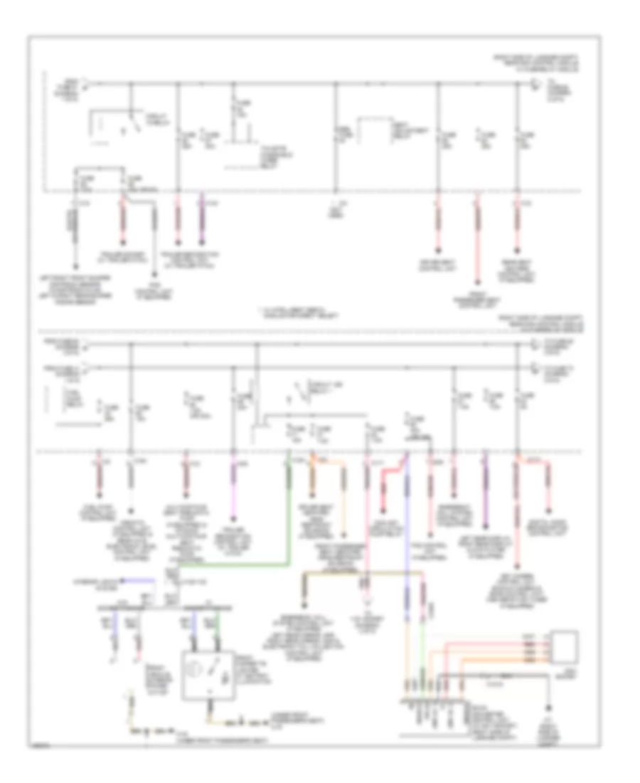
Power Distribution Wiring Diagram, Convertible (5 of 6) for Mercedes-Benz E350 4Matic 2014
List of elements for Power Distribution Wiring Diagram, Convertible (5 of 6) for Mercedes-Benz E350 4Matic 2014:
- (diagram 1 0f 6)
- (diagram 4 0f 6)
- (left rear of engine compt) front sam control module w/ fuse/relay module
- (not used)
- Audio/ comand control panel
- Audio/ comand display & navigation module (if equipped)
- Automatic air conditioning control & operating unit (if equipped)
- C13d
- C2i
- C5c
- C9g
- Command fan motor
- Electronic selector level module control unit
- From fuse 124 g
- From r fuse 31b (diagram 4 0f 6)
- Front sam control module w/ fuse/relay module p
- Fuse 10a
- Fuse 20a
- Fuse 30a
- Fuse 40a
- Fuse 5a
- Fuse 7.5a
- Intelligent servo module for direct select (if equipped)
- Interior fuse box
- Left front lamp unit & right front lamp unit
- Mobile phone electrical connector (if equipped)
- Panoramic sliding roof control module (if equipped)
- Red
- Reserve fuse
- Secondary air injection relay
- Steering column module control unit
- Steering column module control unit (if equipped)
- Stereo multi- function camera
- To fuse 1 (diagram 6 0f 6)
- To fuse 14 (diagram 6 0f 6)
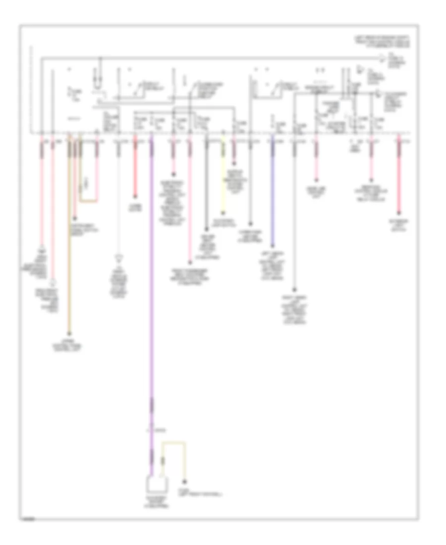
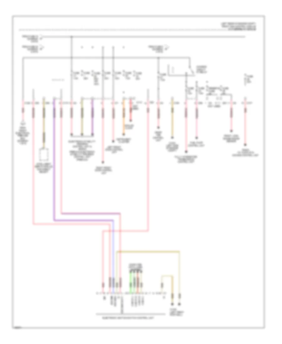
Power Distribution Wiring Diagram, Convertible (6 of 6) for Mercedes-Benz E350 4Matic 2014
List of elements for Power Distribution Wiring Diagram, Convertible (6 of 6) for Mercedes-Benz E350 4Matic 2014:
- (left rear of engine compt) front sam control module w/ fuse/relay module
- (not used)
- 30z
- Analog clock
- C10t
- C11c
- C12s
- C15m
- C17c
- C2i
- C4i
- C5c
- C7i
- C9g
- Can b h
- Can b l
- Can e1 h
- Can e1 l
- Chassis circuit 87 relay
- Computer data lines system
- Electronic ignition switch control unit
- Electronic stability program control unit & (basic) premium electronic stability program control unit (premium)
- Ezs ism
- Ezs sbw
- Ezs sbw batt
- From front electrical prefuse box (diagram 1 of 6)
- From fuse 16 (diagram 5 0f 6)
- From fuse 32 (diagram 5 of 6)
- From fuse 5 (diagram 4 of 6)
- Front long range radar sensor
- Fuel pump control unit
- Fully integrated transmission control unit
- Fuse 10a
- Fuse 20a
- Fuse 25a
- Fuse 30a
- Fuse 50a (or 40a)
- Fuse 5a
- Fuse 7.5a
- Instrument cluster
- Intelligent servo module for direct select
- Left front door control unit
- Me-sfi (me) control unit
- Radio (w/ audio 20 & comand control unit
- Red
- Reserve fuse
- Right front door control unit
- W15/5 (left front footwell)
- W16/3 (left side of engine compt)
Power Distribution Wiring Diagram, Coupe (1 of 6) for Mercedes-Benz E350 4Matic 2014
List of elements for Power Distribution Wiring Diagram, Coupe (1 of 6) for Mercedes-Benz E350 4Matic 2014:
- (not used)
- (right rear of engine compt) front electrical prefuse box
- (w/ eco start stop function) eco start/stop function additional battery relay
- 200a 400a
- 60a
- A/c housing
- Airscarf system control unit (convertible w/ heated seats)
- Alternator
- Am amplifier w/ selection switch
- Am, fm & c2 (zv) antenna amplifier
- Battery sensor
- C116
- C117
- C123
- C124
- C126
- C127
- C18m
- C19i
- C3i
- C8d
- C9i
- Combustion engine & air conditioning w/ integrated control fan motor
- Driver seat control unit
- Driver seat heater control unit (if equipped)
- Eco start/ stop function additional battery
- Eco start/stop function diode
- Electrical power steering control unit (if equipped)
- From fuse a (diagram 1 of 6)
- Front electrical prefuse box (right rear of engine compt)
- Front passenger seat control unit
- Front sam control unit w/ fuse & relay module (left rear of engine compt)
- Fssp
- Fully integrated transmission control unit
- Fully integrated transmission control unit terminal 30 electrical fuse
- Fuse
- Fuse 100a
- Fuse 150a
- Fuse 200a
- Fuse 25a
- Fuse 30a
- Fuse 50a
- Fuse 50a 100a
- Fuse 60a
- Fuse 7.5a
- Fuse 80a
- Ig1
- Im1
- Interior fuse box
- Interior protection & tow-away protection control unit
- M10
- Mg1
- Mg2
- Mr1
- Mr2
- Mr3
- Mr4
- Mr5
- Mr7
- Mr8
- Mr9
- On board electrical system battery
- Pyro fuse
- Quiescent current cutout relay
- Rear sam control unit w/ fuse/ relay module (convertible: in spare wheelwell) (coupe: right side of luggage compt)
- Rear window antenna amplifier 1 (coupe)
- Rear window antenna fm antenna amplifier (coupe) & rear window antenna amplifier 2 (coupe)
- Red
- Res fuse
- Reserve fuse
- Reserve fuse 20a
- Starter
- Stop function
- To circuit 15 relay (diagram 2 of 6)
- To front sam control module w/ fuse/relay module (diagram 4 of 6)
- To front sam control module w/ fuse/relay module (diagram 6 of 6)
- To fuse 150 (diagram 1 of 6)
- To fuse 89 (diagram 2 of 6)
- To reserve fuse 118 (diagram 5 of 6)
- Tv3, fm2 & dab band 3 antenna amplifier
- W/ eco start/ stop function
- W/ seat ventilation
- W/o eco start/
- W/o seat ventilation
- W16/4 (right rear of engine compt)
- W7 (right side of luggage compt)
Power Distribution Wiring Diagram, Coupe (2 of 6) for Mercedes-Benz E350 4Matic 2014
List of elements for Power Distribution Wiring Diagram, Coupe (2 of 6) for Mercedes-Benz E350 4Matic 2014:
- (convertible: in spare wheelwell) (coupe: right side of luggage compt) rear sam control module w/ fuse/relay module
- (diagram 1 of 6)
- (not used)
- 13a
- C11t
- C12i
- C13a
- C14i
- C15h
- C3i
- C89
- Circuit 15 relay
- Circuit 15r relay 1
- Convertible
- Driver seat neck-pro head restraint solenoid
- Emergency call system control unit & telematics services communication module (if equipped)
- From front m sam control module w/ fuse & relay module (diagram 4 of 6)
- From fuse 46 c (diagram 1 0f 6)
- From rear sam control module w/ fuse/relay module (diagram 3 0f 6)
- From reserve fuse 47 d
- From reserve fuse 52 h (diagram 2 0f 6)
- Front cigarette lighter w/ ashtray illumination (w/ smoker package)
- Front passenger seat neck-pro head restraint solenoid
- Front vehicle interior power outlet (w/o smoker package)
- Fuel pump control unit
- Fuel pump relay
- Fuse 15a
- Fuse 20a
- Fuse 20a (or 25a)
- Fuse 30a
- Fuse 40a
- Fuse 5a
- Fuse 7.5a
- Left front bumper distronic sensor, right front bumper distronic sensor, left rear bumper radar sensor & center rear bumper radar sensor (if equipped) right rear bumper radar sensor & collision prevention assist controller unit (w/ active blind spot assist)
- Left front seat ventilation blower regulator (if equipped) & right front seat ventilation blower regulator (if equipped)
- Multicontour seat pneumatic pump (if equipped)
- Nca
- Overhead control panel electronics (w/o can) overhead control panel control module (w/ can)
- Rear control unit
- Red
- Reserve fuse
- Satellite digital audio radio (sdar) control unit (if equipped), backup camera (late production), 360 degree camera control unit & digital audio broadcasting control unit (if equipped)
- Seat adjustment relay
- To fuse 42 (diagram 2 of 6)
- To fuse 73 (diagram 3 0f 6)
- To fuse 85 (diagram 3 0f 6)
- Trailer recognition control unit (w/ trailer hitch)
- Trailer socket
- Vehicle interior power outlet (w/ rear socket)
- W/ smoker package
- W/o can
- W/o smoker package
- W19 (under front passenger seat)
- X18/37
Power Distribution Wiring Diagram, Coupe (3 of 6) for Mercedes-Benz E350 4Matic 2014
List of elements for Power Distribution Wiring Diagram, Coupe (3 of 6) for Mercedes-Benz E350 4Matic 2014:
- (convertible)
- (convertible: in spare wheelwell) (coupe: right side of luggage compt) rear sam control module w/ fuse/relay module
- (coupe)
- (not used)
- (or pnk/red) red
- Adaptive damping system control unit (if equipped)
- C11r
- C11t
- C12i
- C14i
- C15h
- C2g
- C66
- Chassis gateway control unit
- Circuit 15r relay 2
- Compensator/cellular telephone system umts (w/ mobile phone preinstallation w/ universal interface & w/ stationary heater)
- Coolant circulation pump relay (4.6l twin turbo)
- Diagnostic connector
- From fuse 60 (diagram 2 of 6)
- From fuse 84 (diagram 2 0f 6)
- From reserve fuse 91 n (diagram 3 0f 6)
- Fuse 15a
- Fuse 20a
- Fuse 30a
- Fuse 40a 30a
- Fuse 50a
- Fuse 5a
- Fuse 7.5a
- Keyless go control unit (if equipped)
- Left front reversible emergency tensioning retractor (if equipped)
- Media interface control unit (w/ auxiliary jack)
- Parking system control unit (if equipped)
- Radar sensors control unit (if equipped)
- Rear window heated relay
- Red
- Reserve fuse
- Right front reversible emergency tensioning retractor (if equipped)
- Sound system amplifier control unit (if equipped)
- Stationary heater radio remote control receiver (if equipped)
- Stationary heater unit (if equipped)
- Tire pressure monitor control unit (if equipped)
- To fuse 70 (diagram 3 of 6)
- To vehicle interior power outlet (diagram 2 of 6)
- Tv tuner (analog/digital) (if equipped) & tv digital tuner (if equipped)
- Weight sensing system (wss) control unit (if equipped)
Power Distribution Wiring Diagram, Coupe (4 of 6) for Mercedes-Benz E350 4Matic 2014
List of elements for Power Distribution Wiring Diagram, Coupe (4 of 6) for Mercedes-Benz E350 4Matic 2014:
- (left rear of engine compt) front sam control module w/ fuse/relay module
- (not used)
- 16s
- 19i
- C11c
- C14m
- C15m
- C19i
- C1m
- C6i
- C7i
- Circuit 15 relay
- Circuit 15r relay
- Driver seat heater control unit (if equipped)
- Electronic stability program control unit (basic) premium electronic stability program control unit (premium)
- Engine circuit 87 relay
- Exterior light switch
- Fanfare horn relay
- From front electrical prefuse box (diagram 1 of 6)
- Front passenger seat occupied recognition & acsr (if equipped)
- Fuse 10a
- Fuse 15a
- Fuse 20a
- Fuse 30a
- Fuse 31a 15a
- Fuse 31b 15a
- Fuse 7.5a
- Glove box lamp switch
- Glove box socket (if equipped)
- Instrument panel switch group
- Left xenon lamp control unit (w/ xenon) left front lamp unit (w/o xenon)
- Me-sfi (me) control unit
- Nca
- Oil cooler fan motor relay
- Pnk/red
- Rear sam control module w/ fuse/ relay module
- Red
- Right xenon lamp control unit (w/ xenon) right front lamp unit (w/o xenon)
- Starter circuit 50 relay
- To chassis circuit 87 relay (diagram 6 0f 6)
- To front vehicle interior power outlet (diagram 2 of 6)
- To fuse 13 (diagram 5 0f 6)
- To fuse 15 (diagram 5 0f 6)
- Upper control panel control unit
- W15/5 (left front footwell)
- Wiper motor
- Wiper park heater (if equipped)
- Wiper park position heater relay
- X18-c1
- X18-c2
Power Distribution Wiring Diagram, Coupe (5 of 6) for Mercedes-Benz E350 4Matic 2014
List of elements for Power Distribution Wiring Diagram, Coupe (5 of 6) for Mercedes-Benz E350 4Matic 2014:
- (diagram 1 0f 6)
- (diagram 4 0f 6)
- (left rear of engine compt) front sam control module w/ fuse/relay module
- (not used)
- Audio/ comand control panel
- Audio/ comand display & navigation module (if equipped)
- Automatic air conditioning control & operating unit (if equipped)
- C13d
- C2i
- C5c
- C9g
- Command fan motor
- Electronic selector level module control unit
- From fuse 124 g
- From r fuse 31b (diagram 4 0f 6)
- Front sam control module w/ fuse/relay module p
- Fuse 10a
- Fuse 20a
- Fuse 30a
- Fuse 40a
- Fuse 5a
- Fuse 7.5a
- Intelligent servo module for direct select (if equipped)
- Interior fuse box
- Left front lamp unit & right front lamp unit
- Mobile phone electrical connector (if equipped)
- Panoramic sliding roof control module (if equipped)
- Red
- Reserve fuse
- Secondary air injection relay
- Steering column module control unit
- Steering column module control unit (if equipped)
- Stereo multi- function camera
- To fuse 1 (diagram 6 0f 6)
- To fuse 14 (diagram 6 0f 6)
Power Distribution Wiring Diagram, Coupe (6 of 6) for Mercedes-Benz E350 4Matic 2014
List of elements for Power Distribution Wiring Diagram, Coupe (6 of 6) for Mercedes-Benz E350 4Matic 2014:
- (left rear of engine compt) front sam control module w/ fuse/relay module
- (not used)
- 30z
- Analog clock
- C10t
- C11c
- C12s
- C15m
- C17c
- C2i
- C4i
- C5c
- C7i
- C9g
- Can b h
- Can b l
- Can e1 h
- Can e1 l
- Chassis circuit 87 relay
- Computer data lines system
- Electronic ignition switch control unit
- Electronic stability program control unit & (basic) premium electronic stability program control unit (premium)
- Ezs ism
- Ezs sbw
- Ezs sbw batt
- From front electrical prefuse box (diagram 1 of 6)
- From fuse 16 (diagram 5 0f 6)
- From fuse 32 (diagram 5 of 6)
- From fuse 5 (diagram 4 of 6)
- Front long range radar sensor
- Fuel pump control unit
- Fully integrated transmission control unit
- Fuse 10a
- Fuse 20a
- Fuse 25a
- Fuse 30a
- Fuse 50a (or 40a)
- Fuse 5a
- Fuse 7.5a
- Instrument cluster
- Intelligent servo module for direct select
- Left front door control unit
- Me-sfi (me) control unit
- Radio (w/ audio 20 & comand control unit
- Red
- Reserve fuse
- Right front door control unit
- W15/5 (left front footwell)
- W16/3 (left side of engine compt)
Power Distribution Wiring Diagram, Sedan (1 of 5) for Mercedes-Benz E350 4Matic 2014
List of elements for Power Distribution Wiring Diagram, Sedan (1 of 5) for Mercedes-Benz E350 4Matic 2014:
- (diagram 1 of 5)
- (or red)
- (right rear of engine compt) front electrical prefuse box
- 150a
- 20a
- 3.5l hybrid
- A/c housing (w/ 2-zone thermatic & 3-zone thermotronic)
- Additional battery relay circuit 30 fuse additional fuse (spare wheelwell, behind battery)
- Airmatic relay (if equipped & w/ electronic level control w/ hydraulics)
- Alarm siren (if equipped)
- Alternator
- B1s
- Battery sensor
- C12i
- C18m
- C19i
- C1a
- C1v
- C2v
- C3i
- C8d
- C9i
- Combustion engine & air conditioning w/ integrated control fan motor (w/ fan motor 800w & 650w)
- Coolant circulation pump relay (4.6l turbo)
- Eco start/ stop function additional battery
- Eco start/ stop function circuit 30 cable connector
- Eco start/stop function additional battery relay (under right side of luggage compt floor)
- Eco start/stop function diode
- Electrical power steering control unit (if equipped)
- Except 3.5l hybrid
- From fuse 157 a
- From rear prefuse box (diagram 1 of 5)
- Front electrical prefuse box (right rear of engine compt)
- Front sam control unit w/ fuse & relay module (left rear of engine compt)
- Fuse 100a
- Fuse 150a
- Fuse 150a (or 100a)
- Fuse 150a 350a
- Fuse 15a
- Fuse 20a
- Fuse 30a
- Fuse 400a
- Fuse 400a (except 3.5l hybrid)
- Fuse 40a
- Fuse 50a
- Fuse 50a 80a
- Fuse 60a
- Fuse 7.5a
- Glow output stage
- Glow output stage (3.0l turbo diesel)
- Ig1
- Im1
- Intelligent servo module for direct select (if equipped)
- Interference suppression capacitor
- Interior fuse box (except 3.5l hybrid)
- Interior protection & tow-away protection control unit (if equipped)
- Ism
- Left rear door control unit
- M10
- Mr1
- Mr4 red
- Mr5 red
- Mr6
- Mr7
- Mr8
- Mrg2
- On-board electrical system battery (w/ front battery)
- Ptc heater booster (if equipped, w/ 2-zone thermatic & 3-zone thermotronic)
- Pyrofuse
- Quiescent current cutout relay
- Rear blower motor (w/ 3-zone thermotronic)
- Rear on-board electrical system battery (w/ rear battery)
- Rear prefuse box (right front of luggage compt floor)
- Rear sam control module w/ fuse/ relay module (right side of luggage compt)
- Rear sam control unit w/ fuse & relay module circuit 30 fuse
- Rear window antenna amplifier 1, fm 1, am, cl (zv) & keyless go antenna amplifier
- Red
- Red mr3
- Red mr9
- Right front door control unit
- Starter
- Stationary heater fuse
- Stationary heater unit (3.5l hybrid)
- Stationary heater unit (except hybrid)
- Terminal block (circuit 30)
- To circuit 15 relay (diagram 2 of 5)
- To front sam control module w/ fuse/ relay module (diagram 4 of 5)
- To front sam control module w/ fuse/ relay module (diagram 5 of 5)
- To front sam control module w/ fuse/relay module (diagram 5 of 5)
- To fuse 155 (diagram 1 of 5)
- To fuse 42 (diagram 2 of 5)
- To hybrid fuse & relay module (diagram 4 of 5)
- To rear sam control module w/ fuse/ relay module (diagram 1 of 5)
- Trunk lid control unit (sedan) tailgate control unit (wagon)
- W/ eco start/ stop system
- W/ front battery
- W/ rear battery
- W/o eco start/ stop system
- W16/4 (right rear of engine compt)
- W2 (right side of engine compt)
- W7/8 (right side of luggage compt)
Power Distribution Wiring Diagram, Sedan (2 of 5) for Mercedes-Benz E350 4Matic 2014
List of elements for Power Distribution Wiring Diagram, Sedan (2 of 5) for Mercedes-Benz E350 4Matic 2014:
- (diagram 1 of 5)
- (not used)
- (or 5a)
- (right side of luggage compt) rear sam control module w/ fuse/relay module
- (under front passenger's seat) w19
- 15r (1)
- 230v ac 1
- 230v ac 2
- 230v socket
- 360° camera control unit, backup camera & sdar control unit/ high definition tuner (if equipped)
- Aag
- Airmatic control unit (if equipped) & rear axle electronic level control unit (if equipped)
- C11t
- C12i
- C13a
- C15h
- C3i
- Circuit 15 relay
- Circuit 15r relay 1
- Coolant circulation pump relay
- Dc/ac converter control unit (w/ 230v socket) (right side of luggage compt)
- Digital audio broadcasting control unit
- Driver seat control unit
- Driver seat neck-pro head restraint solenoid (if equipped)
- Emergency call system control unit (if equipped)
- Emergency call system control unit (if equipped) left rear mirror lamp, right rear mirror lamp & electronic toll collection control unit (if equipped)
- Enable
- From fuse 41 c (diagram 1 0f 5)
- From fuse 61 b
- From fuse 63 (diagram g 2 0f 5)
- Front cigarette lighter w/ ashtray illumination
- Front passenger seat control unit
- Front passenger seat neck-pro head restraint solenoid (if equipped)
- Front vehicle interior power outlet
- Fuel pump control unit (if equipped)
- Fuel pump relay
- Fuse 15a
- Fuse 20a
- Fuse 25a
- Fuse 30a
- Fuse 40a (or 15a)
- Fuse 5a
- Fuse 7.5a
- Fuse 7.5a (or 30a)
- Interior lights system
- Left rear display, right rear display & dvd player (if equipped)
- Left/right front bumper distronic sensor (w/distronic plus) left & right rear bumper radar sensor
- Module for direct select
- Multicontour seat pneumatic pump (if equipped) & dynamic multicontour seat pneumatic pump (if equipped)
- Nca
- Pas control unit (if equipped)
- Rear seat heaters control unit (if equipped)
- Red
- Res fuse
- Scr
- Seat adjustment relay
- Tailgate windshield wiper relay
- To 115v socket (diagram 3 of 5)
- To fuse 68 (diagram 2 of 5)
- To fuse 73 (diagram 3 0f 5)
- To fuse 85 (diagram 3 0f 5)
- Trailer recognition control unit (w/ trailer hitch)
- Trailer socket (w/ trailer hitch)
- W/ intelligent servo
- W/ smoker package
- W/o smoker package
- W19 (under front passenger's seat)
- W7 (right side of luggage compt)
- X137/8
Power Distribution Wiring Diagram, Sedan (3 of 5) for Mercedes-Benz E350 4Matic 2014
List of elements for Power Distribution Wiring Diagram, Sedan (3 of 5) for Mercedes-Benz E350 4Matic 2014:
- (not used)
- (right side of luggage compt) (w/ 115v socket) dc/ac converter control unit
- (right side of luggage compt) rear sam control module w/ fuse/relay module
- (right side of luggage compt) w7
- (w/ rear socket) load compartment socket
- 115v ac1
- 115v ac2
- 115v socket
- 30g
- C10r
- C11t
- C12i
- C14i
- C15h
- C2g
- C3i
- Cellular telephone system antenna amplifier/compensator unit (comfort telephony w/ compensator stationary heater) & mobile phone electrical connector (if equipped & comfort telephony w/o compensator)
- Circuit 15r relay 2
- Diagnostic connector
- From fuse 67 j (diagram 3 0f 5)
- From fuse 84 (diagram 2 of 5)
- From fuse 87 (diagram 2 0f 5)
- From rear sam control module w/ fuse relay module v (diagram 2 of 5)
- Fuse 10a
- Fuse 15a
- Fuse 20a
- Fuse 25a
- Fuse 40a
- Fuse 50a
- Fuse 5a
- Fuse 7.5a
- Heated rear window relay
- Keyless go control unit
- Left front reversible emergency tensioning retractor (if equipped)
- Left front seat ventilation blower regulator (if equipped)
- Media interface control unit (if equipped)
- Parking system control unit (if equipped)
- Radar sensors control unit (w/ distronic plus, blind spot assist) & chassis gateway control unit
- Rear bass speaker & sound system amplifier control unit (if equipped)
- Rear bass speaker amplifier (if equipped)
- Rear center console power outlet
- Rear switching module (w/ trunk lid opening/closing sensor)
- Red
- Res fuse
- Right front lamp unit & left front lamp unit
- Right front lamp unit, left front lamp unit & keyless go control unit (if equipped)
- Right front reversible emergency tensioning retractor (if equipped)
- Right front seat ventilation blower regulator (if equipped)
- Stationary heater unit
- Steering column module control unit
- Telematics services communication module (if equipped)
- Tire pressure monitor control unit (if equipped)
- To front sam control unit w/ fuse & relay module (diagram 4 of 5)
- To fuse 70 (diagram 3 of 5)
- Tv tuner (analog/digital) (if equipped & w/ ece)
- W19 (under front passenger's seat)
- W7 (right side of luggage compt)
- Weight sensing system (wss) control unit (if equipped)
Power Distribution Wiring Diagram, Sedan (4 of 5) for Mercedes-Benz E350 4Matic 2014
List of elements for Power Distribution Wiring Diagram, Sedan (4 of 5) for Mercedes-Benz E350 4Matic 2014:
- (diagram 4 0f 5)
- (left rear of engine compt) front sam control module w/ fuse/relay module
- (not used)
- Analog clock
- Audio/ comand display
- Audio/comand control panel (if equipped)
- Automatic air conditioning & control operating unit (w/ 2-zone thermatic & 3-zone thermotronic)
- Automatic transmission mode button & suspension button group (w/ airmatic)
- Battery management system control unit
- C10t
- C11c
- C13d
- C14m
- C15m
- C16s red
- C1m
- C2i
- C5c
- C6i
- C7i
- C8s
- C9g
- Circuit 15 relay
- Circuit 15r relay
- Electronic refrigerant compressor (3.5l hybrid)
- Electronic selector level module control unit (if equipped)
- Electronic stability program control unit (basic) premium electronic stability program control unit (premium)
- Engine circuit 87 relay
- Exterior light switch (if equipped)
- Fanfare horn relay
- From front electrical prefuse box (diagram 1 of 5)
- From front electrical w prefuse box (diagram 1 0f 5)
- From front sam control module w/ fuse/ relay module (diagram 4 of 5)
- From fuse 31b n
- From o engine circuit 87 relay (diagram 4 0f 5)
- From rear sam control module w/ fuse/relay module (diagram 3 0f 5)
- Front passenger seat occupied recognition & ascr
- Front sam control module w/ fuse/relay module (left rear of engine compt)
- Fuse 10a
- Fuse 15a
- Fuse 20a
- Fuse 20a (or 7.5a)
- Fuse 30a
- Fuse 31a 15a
- Fuse 31b 15a
- Fuse 40a
- Fuse 5a
- Fuse 7.5a
- Glove box lamp switch
- Glove box socket (if equipped)
- Hybrid fuse & relay module
- Hybrid power electronics coolant circulation pump relay
- Left front lamp unit
- Me-sfi (me) control unit (except 3.0l turbo diesel) & cdi control unit (3.0l turbo diesel)
- Multi- function camera (w/ mono multi-function camera) stereo multi- function camera (if equipped)
- Navigation module (if equipped) command fan motor (if equipped)
- Overhead control panel control unit (w/ tilting/ sliding roof) & panoramic sliding roof control module (if equipped)
- Pnk/red
- Power electronics control unit (3.5l hybrid)
- Pyrotechnical separator
- Rear sam control module w/ fuse/ relay module
- Red
- Right front lamp unit
- Secondary air injection relay
- Starter circuit 50 relay
- Steering column module control unit
- Stop lamp switch (w/ esp basic & esp premium)
- To chassis circuit 87 relay (diagram 5 0f 5)
- To engine circuit 87 relay (diagram 4 0f 5)
- To fuse 1 (diagram 5 0f 5)
- To fuse 14 (diagram 5 0f 5)
- To fuse 15 (diagram 4 0f 5)
- To secondary air injection relay (diagram 4 0f 5)
- Trans- mission oil auxi- liary pump relay
- Transmission oil auxiliary pump control unit
- Transmission oil cooling coolant circulation pump relay
- Upper control panel control unit
- Vacuum pump relay (+)
- Vacuum pump relay (-)
- W/o wss
- W15/7 (right front footwell)
- Weight sensing system control unit
- Wiper motor
- Wiper park heater (if equipped)
- Wiper park position heater relay
- X18-c1
- X83/11-c2
Power Distribution Wiring Diagram, Sedan (5 of 5) for Mercedes-Benz E350 4Matic 2014
List of elements for Power Distribution Wiring Diagram, Sedan (5 of 5) for Mercedes-Benz E350 4Matic 2014:
- (left rear of engine compt) front sam control module w/ fuse/relay module
- (not used)
- 30z
- Additional battery
- Automatic transmission neutral position switch (base of shift lever assembly)
- C10t
- C11c
- C12s
- C15m
- C17c
- C19i
- C2i
- C4i
- C5c
- C7i
- C9g
- Can-b h
- Can-b l
- Can-e1 h
- Can-e1 l
- Cdi control unit (3.0l turbo diesel)
- Chassis circuit 87 relay
- Computer data lines system
- Data
- Electronic ignition switch control unit
- Electronic stability program control unit (basic), premium electronic stability program control unit (premium) & regenerative braking system control unit (if equipped)
- Electronic steering lock control unit
- Ezs backup
- From front electrical prefuse box (diagram 1 of 5)
- From fuse 16 (diagram 4 of 5)
- From fuse 32 (diagram 4 of 5)
- From fuse 5 u (diagram 4 of 5)
- From rear prefuse box (diagram 1 of 5)
- Front long range radar sensor & collision prevention assist controller (if equipped)
- Front sam control module w/ fuse/relay module
- Fuel pump control unit (3.0l turbo diesel)
- Fully integrated transmission control unit
- Fuse 10a
- Fuse 20a
- Fuse 25a
- Fuse 30a
- Fuse 40a
- Fuse 5a
- Fuse 7.5a
- Fuse box (left end of dash)
- Hybrid fuse & relay module
- Instrument cluster
- Intelligent servo module for direct select (if equipped)
- Left front door control unit
- Me-sfi (me) control unit (except 3.0l turbo diesel) &
- Module for direct select
- Night vision assist control unit
- P not
- Radio (w/ audio 20) & comand control unit (if equipped)
- Red
- Right rear door control unit
- W/ front battery
- W/ intelligent servo
- W/ keyless go
- W/ rear battery
- W/o direct select
- W/o keyless go
- W15/5 (left front footwell)
- X190-c1
Power Distribution Wiring Diagram, Wagon (1 of 5) for Mercedes-Benz E350 4Matic 2014
List of elements for Power Distribution Wiring Diagram, Wagon (1 of 5) for Mercedes-Benz E350 4Matic 2014:
- (diagram 1 of 5)
- (or red)
- (right rear of engine compt) front electrical prefuse box
- 150a
- 20a
- 3.5l hybrid
- A/c housing (w/ 2-zone thermatic & 3-zone thermotronic)
- Additional battery relay circuit 30 fuse additional fuse (spare wheelwell, behind battery)
- Airmatic relay (if equipped & w/ electronic level control w/ hydraulics)
- Alarm siren (if equipped)
- Alternator
- B1s
- Battery sensor
- C12i
- C18m
- C19i
- C1a
- C1v
- C2v
- C3i
- C8d
- C9i
- Combustion engine & air conditioning w/ integrated control fan motor (w/ fan motor 800w & 650w)
- Coolant circulation pump relay (4.6l turbo)
- Eco start/ stop function additional battery
- Eco start/ stop function circuit 30 cable connector
- Eco start/stop function additional battery relay (under right side of luggage compt floor)
- Eco start/stop function diode
- Electrical power steering control unit (if equipped)
- Except 3.5l hybrid
- From fuse 157 a
- From rear prefuse box (diagram 1 of 5)
- Front electrical prefuse box (right rear of engine compt)
- Front sam control unit w/ fuse & relay module (left rear of engine compt)
- Fuse 100a
- Fuse 150a
- Fuse 150a (or 100a)
- Fuse 150a 350a
- Fuse 15a
- Fuse 20a
- Fuse 30a
- Fuse 400a
- Fuse 400a (except 3.5l hybrid)
- Fuse 40a
- Fuse 50a
- Fuse 50a 80a
- Fuse 60a
- Fuse 7.5a
- Glow output stage
- Glow output stage (3.0l turbo diesel)
- Ig1
- Im1
- Intelligent servo module for direct select (if equipped)
- Interference suppression capacitor
- Interior fuse box (except 3.5l hybrid)
- Interior protection & tow-away protection control unit (if equipped)
- Ism
- Left rear door control unit
- M10
- Mr1
- Mr4 red
- Mr5 red
- Mr6
- Mr7
- Mr8
- Mrg2
- On-board electrical system battery (w/ front battery)
- Ptc heater booster (if equipped, w/ 2-zone thermatic & 3-zone thermotronic)
- Pyrofuse
- Quiescent current cutout relay
- Rear blower motor (w/ 3-zone thermotronic)
- Rear on-board electrical system battery (w/ rear battery)
- Rear prefuse box (right front of luggage compt floor)
- Rear sam control module w/ fuse/ relay module (right side of luggage compt)
- Rear sam control unit w/ fuse & relay module circuit 30 fuse
- Rear window antenna amplifier 1, fm 1, am, cl (zv) & keyless go antenna amplifier
- Red
- Red mr3
- Red mr9
- Right front door control unit
- Starter
- Stationary heater fuse
- Stationary heater unit (3.5l hybrid)
- Stationary heater unit (except hybrid)
- Terminal block (circuit 30)
- To circuit 15 relay (diagram 2 of 5)
- To front sam control module w/ fuse/ relay module (diagram 4 of 5)
- To front sam control module w/ fuse/ relay module (diagram 5 of 5)
- To front sam control module w/ fuse/relay module (diagram 5 of 5)
- To fuse 155 (diagram 1 of 5)
- To fuse 42 (diagram 2 of 5)
- To hybrid fuse & relay module (diagram 4 of 5)
- To rear sam control module w/ fuse/ relay module (diagram 1 of 5)
- Trunk lid control unit (sedan) tailgate control unit (wagon)
- W/ eco start/ stop system
- W/ front battery
- W/ rear battery
- W/o eco start/ stop system
- W16/4 (right rear of engine compt)
- W2 (right side of engine compt)
- W7/8 (right side of luggage compt)
Power Distribution Wiring Diagram, Wagon (2 of 5) for Mercedes-Benz E350 4Matic 2014
List of elements for Power Distribution Wiring Diagram, Wagon (2 of 5) for Mercedes-Benz E350 4Matic 2014:
- (diagram 1 of 5)
- (not used)
- (or 5a)
- (right side of luggage compt) rear sam control module w/ fuse/relay module
- (under front passenger's seat) w19
- 15r (1)
- 230v ac 1
- 230v ac 2
- 230v socket
- 360° camera control unit, backup camera & sdar control unit/ high definition tuner (if equipped)
- Aag
- Airmatic control unit (if equipped) & rear axle electronic level control unit (if equipped)
- C11t
- C12i
- C13a
- C15h
- C3i
- Circuit 15 relay
- Circuit 15r relay 1
- Coolant circulation pump relay
- Dc/ac converter control unit (w/ 230v socket) (right side of luggage compt)
- Digital audio broadcasting control unit
- Driver seat control unit
- Driver seat neck-pro head restraint solenoid (if equipped)
- Emergency call system control unit (if equipped)
- Emergency call system control unit (if equipped) left rear mirror lamp, right rear mirror lamp & electronic toll collection control unit (if equipped)
- Enable
- From fuse 41 c (diagram 1 0f 5)
- From fuse 61 b
- From fuse 63 (diagram g 2 0f 5)
- Front cigarette lighter w/ ashtray illumination
- Front passenger seat control unit
- Front passenger seat neck-pro head restraint solenoid (if equipped)
- Front vehicle interior power outlet
- Fuel pump control unit (if equipped)
- Fuel pump relay
- Fuse 15a
- Fuse 20a
- Fuse 25a
- Fuse 30a
- Fuse 40a (or 15a)
- Fuse 5a
- Fuse 7.5a
- Fuse 7.5a (or 30a)
- Interior lights system
- Left rear display, right rear display & dvd player (if equipped)
- Left/right front bumper distronic sensor (w/distronic plus) left & right rear bumper radar sensor
- Module for direct select
- Multicontour seat pneumatic pump (if equipped) & dynamic multicontour seat pneumatic pump (if equipped)
- Nca
- Pas control unit (if equipped)
- Rear seat heaters control unit (if equipped)
- Red
- Res fuse
- Scr
- Seat adjustment relay
- Tailgate windshield wiper relay
- To 115v socket (diagram 3 of 5)
- To fuse 68 (diagram 2 of 5)
- To fuse 73 (diagram 3 0f 5)
- To fuse 85 (diagram 3 0f 5)
- Trailer recognition control unit (w/ trailer hitch)
- Trailer socket (w/ trailer hitch)
- W/ intelligent servo
- W/ smoker package
- W/o smoker package
- W19 (under front passenger's seat)
- W7 (right side of luggage compt)
- X137/8
Power Distribution Wiring Diagram, Wagon (3 of 5) for Mercedes-Benz E350 4Matic 2014
List of elements for Power Distribution Wiring Diagram, Wagon (3 of 5) for Mercedes-Benz E350 4Matic 2014:
- (not used)
- (right side of luggage compt) (w/ 115v socket) dc/ac converter control unit
- (right side of luggage compt) rear sam control module w/ fuse/relay module
- (right side of luggage compt) w7
- (w/ rear socket) load compartment socket
- 115v ac1
- 115v ac2
- 115v socket
- 30g
- C10r
- C11t
- C12i
- C14i
- C15h
- C2g
- C3i
- Cellular telephone system antenna amplifier/compensator unit (comfort telephony w/ compensator stationary heater) & mobile phone electrical connector (if equipped & comfort telephony w/o compensator)
- Circuit 15r relay 2
- Diagnostic connector
- From fuse 67 j (diagram 3 0f 5)
- From fuse 84 (diagram 2 of 5)
- From fuse 87 (diagram 2 0f 5)
- From rear sam control module w/ fuse relay module v (diagram 2 of 5)
- Fuse 10a
- Fuse 15a
- Fuse 20a
- Fuse 25a
- Fuse 40a
- Fuse 50a
- Fuse 5a
- Fuse 7.5a
- Heated rear window relay
- Keyless go control unit
- Left front reversible emergency tensioning retractor (if equipped)
- Left front seat ventilation blower regulator (if equipped)
- Media interface control unit (if equipped)
- Parking system control unit (if equipped)
- Radar sensors control unit (w/ distronic plus, blind spot assist) & chassis gateway control unit
- Rear bass speaker & sound system amplifier control unit (if equipped)
- Rear bass speaker amplifier (if equipped)
- Rear center console power outlet
- Rear switching module (w/ trunk lid opening/closing sensor)
- Red
- Res fuse
- Right front lamp unit & left front lamp unit
- Right front lamp unit, left front lamp unit & keyless go control unit (if equipped)
- Right front reversible emergency tensioning retractor (if equipped)
- Right front seat ventilation blower regulator (if equipped)
- Stationary heater unit
- Steering column module control unit
- Telematics services communication module (if equipped)
- Tire pressure monitor control unit (if equipped)
- To front sam control unit w/ fuse & relay module (diagram 4 of 5)
- To fuse 70 (diagram 3 of 5)
- Tv tuner (analog/digital) (if equipped & w/ ece)
- W19 (under front passenger's seat)
- W7 (right side of luggage compt)
- Weight sensing system (wss) control unit (if equipped)
Power Distribution Wiring Diagram, Wagon (4 of 5) for Mercedes-Benz E350 4Matic 2014
List of elements for Power Distribution Wiring Diagram, Wagon (4 of 5) for Mercedes-Benz E350 4Matic 2014:
- (diagram 4 0f 5)
- (left rear of engine compt) front sam control module w/ fuse/relay module
- (not used)
- Analog clock
- Audio/ comand display
- Audio/comand control panel (if equipped)
- Automatic air conditioning & control operating unit (w/ 2-zone thermatic & 3-zone thermotronic)
- Automatic transmission mode button & suspension button group (w/ airmatic)
- Battery management system control unit
- C10t
- C11c
- C13d
- C14m
- C15m
- C16s red
- C1m
- C2i
- C5c
- C6i
- C7i
- C8s
- C9g
- Circuit 15 relay
- Circuit 15r relay
- Electronic refrigerant compressor (3.5l hybrid)
- Electronic selector level module control unit (if equipped)
- Electronic stability program control unit (basic) premium electronic stability program control unit (premium)
- Engine circuit 87 relay
- Exterior light switch (if equipped)
- Fanfare horn relay
- From front electrical prefuse box (diagram 1 of 5)
- From front electrical w prefuse box (diagram 1 0f 5)
- From front sam control module w/ fuse/ relay module (diagram 4 of 5)
- From fuse 31b n
- From o engine circuit 87 relay (diagram 4 0f 5)
- From rear sam control module w/ fuse/relay module (diagram 3 0f 5)
- Front passenger seat occupied recognition & ascr
- Front sam control module w/ fuse/relay module (left rear of engine compt)
- Fuse 10a
- Fuse 15a
- Fuse 20a
- Fuse 20a (or 7.5a)
- Fuse 30a
- Fuse 31a 15a
- Fuse 31b 15a
- Fuse 40a
- Fuse 5a
- Fuse 7.5a
- Glove box lamp switch
- Glove box socket (if equipped)
- Hybrid fuse & relay module
- Hybrid power electronics coolant circulation pump relay
- Left front lamp unit
- Me-sfi (me) control unit (except 3.0l turbo diesel) & cdi control unit (3.0l turbo diesel)
- Multi- function camera (w/ mono multi-function camera) stereo multi- function camera (if equipped)
- Navigation module (if equipped) command fan motor (if equipped)
- Overhead control panel control unit (w/ tilting/ sliding roof) & panoramic sliding roof control module (if equipped)
- Pnk/red
- Power electronics control unit (3.5l hybrid)
- Pyrotechnical separator
- Rear sam control module w/ fuse/ relay module
- Red
- Right front lamp unit
- Secondary air injection relay
- Starter circuit 50 relay
- Steering column module control unit
- Stop lamp switch (w/ esp basic & esp premium)
- To chassis circuit 87 relay (diagram 5 0f 5)
- To engine circuit 87 relay (diagram 4 0f 5)
- To fuse 1 (diagram 5 0f 5)
- To fuse 14 (diagram 5 0f 5)
- To fuse 15 (diagram 4 0f 5)
- To secondary air injection relay (diagram 4 0f 5)
- Trans- mission oil auxi- liary pump relay
- Transmission oil auxiliary pump control unit
- Transmission oil cooling coolant circulation pump relay
- Upper control panel control unit
- Vacuum pump relay (+)
- Vacuum pump relay (-)
- W/o wss
- W15/7 (right front footwell)
- Weight sensing system control unit
- Wiper motor
- Wiper park heater (if equipped)
- Wiper park position heater relay
- X18-c1
- X83/11-c2
Power Distribution Wiring Diagram, Wagon (5 of 5) for Mercedes-Benz E350 4Matic 2014
List of elements for Power Distribution Wiring Diagram, Wagon (5 of 5) for Mercedes-Benz E350 4Matic 2014:
- (left rear of engine compt) front sam control module w/ fuse/relay module
- (not used)
- 30z
- Additional battery
- Automatic transmission neutral position switch (base of shift lever assembly)
- C10t
- C11c
- C12s
- C15m
- C17c
- C19i
- C2i
- C4i
- C5c
- C7i
- C9g
- Can-b h
- Can-b l
- Can-e1 h
- Can-e1 l
- Cdi control unit (3.0l turbo diesel)
- Chassis circuit 87 relay
- Computer data lines system
- Data
- Electronic ignition switch control unit
- Electronic stability program control unit (basic), premium electronic stability program control unit (premium) & regenerative braking system control unit (if equipped)
- Electronic steering lock control unit
- Ezs backup
- From front electrical prefuse box (diagram 1 of 5)
- From fuse 16 (diagram 4 of 5)
- From fuse 32 (diagram 4 of 5)
- From fuse 5 u (diagram 4 of 5)
- From rear prefuse box (diagram 1 of 5)
- Front long range radar sensor & collision prevention assist controller (if equipped)
- Front sam control module w/ fuse/relay module
- Fuel pump control unit (3.0l turbo diesel)
- Fully integrated transmission control unit
- Fuse 10a
- Fuse 20a
- Fuse 25a
- Fuse 30a
- Fuse 40a
- Fuse 5a
- Fuse 7.5a
- Fuse box (left end of dash)
- Hybrid fuse & relay module
- Instrument cluster
- Intelligent servo module for direct select (if equipped)
- Left front door control unit
- Me-sfi (me) control unit (except 3.0l turbo diesel) &
- Module for direct select
- Night vision assist control unit
- P not
- Radio (w/ audio 20) & comand control unit (if equipped)
- Red
- Right rear door control unit
- W/ front battery
- W/ intelligent servo
- W/ keyless go
- W/ rear battery
- W/o direct select
- W/o keyless go
- W15/5 (left front footwell)
- X190-c1