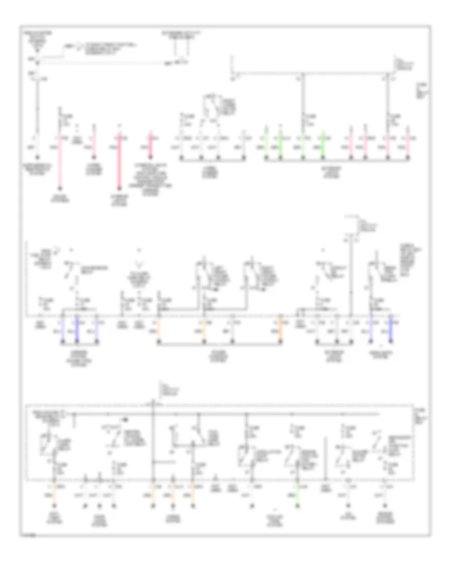
POWER DISTRIBUTION
Power Distribution Wiring Diagram (1 of 4) for Mercedes-Benz ML320 2000

List of elements for Power Distribution Wiring Diagram (1 of 4) for Mercedes-Benz ML320 2000:
- (not used)
- (right wheelwell, in luggage compt) g405
- 15c
- 15r
- A/c system
- A10
- Abs system
- Accy
- Alarm siren
- All activity module
- Battery
- C/b
- C/c
- C/d
- C/e
- C/f
- Cargo area connector
- Circuit relay
- Combination switch
- D/a
- Data link connector (dlc) (dtc readout)
- Engine control module (me-sfi)
- Engine controls system
- Engine controls system, anti-lock brakes system, transmissions system
- Engine controls systems
- Extended activity module (eam)
- Exterior lights system
- F23
- From e fuse 18 (diagram 1 of 4)
- From f fuse 19 (diagram 1 of 4)
- From fuse 13 (diagram 1 of 4)
- Fuel pump relay
- Fuel pump with fuel level sensor
- Fuse & relay box
- Fuse & relay box (in left side of engine compt, in "e" box)
- Fuse 10a
- Fuse 15a
- Fuse 20a
- Fuse 25a
- Fuse 30a (or 40a)
- Fuse 40a
- Fuse 7.5a
- G123 (right side of firewall)
- Generator
- Headlights system
- Instrument cluster
- Instrument cluster system
- Interior lights system, trip computer control module
- M/a
- M/c
- Mirrors system
- Ml/a
- Mr/c
- Mr/d
- Mr/e
- Off
- P/a
- P/b
- P/c
- P/d
- P/e
- P30
- Pnk
- Power tops system
- Red
- Run
- Sound systems
- Start
- Starter
- Starter key switch (closed with key in starter switch)
- Starter relay
- Starter switch
- Steering angle sensor
- Tan
- To convenience relay (diagram 2 of 4)
- To fuel pump relay (diagram 1 of 4)
- To fuse 10 (diagram 2 of 4)
- To fuse 20 (diagram 1 of 4)
- To fuse 21 (diagram 1 of 4)
- To rear fog lamp relay (diagram 3 of 4)
- To right front footwell fuse & relay box (diagram 4 of 4)
- Trailer hitch socket
- Transfer case control module
- X12/3
- X18/3
- X22
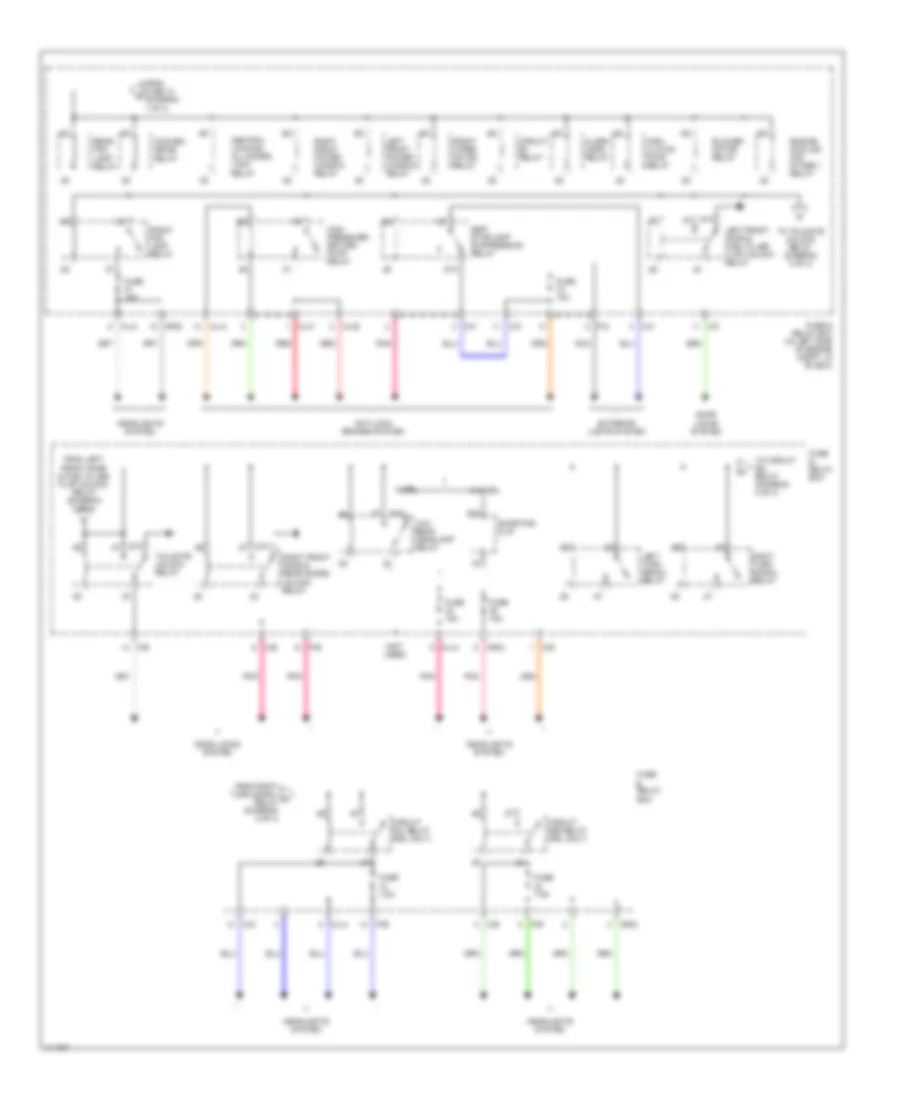
Power Distribution Wiring Diagram (2 of 4) for Mercedes-Benz ML320 2000
List of elements for Power Distribution Wiring Diagram (2 of 4) for Mercedes-Benz ML320 2000:
- (diagram 2 of 4)
- (not used)
- 87a
- A/c system
- Alarm horn relay
- All activity module
- Anti- theft system
- Blower motor relay
- C/b
- C/d
- C/e
- C/f
- C/g
- C3 b5
- Central locking, all doors lock relay
- Circuit relay
- Circulation pump relay
- Convenience relay
- Cooling fans system
- D/a
- Door locks system
- Engine control systems
- Engine cooling fan stage 1 relay
- Extended activity module (eam)
- Exterior lights system
- From conven- ience relay i
- From g fuel pump relay (diagram 1 of 4)
- From starter switch (diagram 1 of 4)
- Front wiper motor relay
- Fuse & relay box
- Fuse & relay box (in left side of engine compt, in "e" box)
- Fuse 10a
- Fuse 15a
- Fuse 20a
- Fuse 25a
- Fuse 30a
- Fuse 40a
- Fuse 7.5a
- Headlights system
- Horns system
- Interior lights system
- Interior lights system, trip computer control module, garage door opener transmitter, mirrors system
- Left front power window relay
- M/a
- Mirrors system, power tops system
- Ml/a
- Ml/b
- Mr/a
- Mr/c
- Mr/d
- Mr/f
- P/b
- P/c
- P/d
- P/e
- Pnk
- Power windows system
- Rear fog lamp relay
- Right front power window relay
- Secondary air injection pump relay
- Sound systems
- To alarm horn relay (diagram 2 of 4)
- To right front footwell fuse & relay box (diagram 4 of 4)
- Two- tone horn relay
- Wiper/ washer system
Power Distribution Wiring Diagram (3 of 4) for Mercedes-Benz ML320 2000
List of elements for Power Distribution Wiring Diagram (3 of 4) for Mercedes-Benz ML320 2000:
- (not used)
- 87a
- Alarm horn relay
- Anti-lock brakes system
- Blower motor relay
- C/c
- C/d
- C/e
- C/f
- C/h
- Central locking, all doors lock relay
- Circ- ulaton pump relay
- Circuit 58l relay (drl only)
- Circuit 58r relay (drl only)
- Circuit relay
- Conven- ience relay
- Door locks system
- Engine cooling fan stage 1 relay
- Esp/ stoplamp suppression relay
- Exterior lights system
- From fuse 13 (diagram 1 of 4)
- From left front door & fuel filler flap unlock relay (diagram 3 of 4)
- From right turn signal k relay (diagram 3 of 4)
- Front fog lamp relay
- Front wiper motor relay
- Fuse & relay box
- Fuse & relay box (in left side of engine compt, in "e" box)
- Fuse 10a
- Fuse 15a
- Fuse 7.5a
- Headlights system
- High pressure/ return pump relay
- Left front door & fuel filler flap unlock relay
- Left front power window relay
- Left turn signal relay
- Low beam headlamp relay
- Ml/a
- Ml/b
- Ml/c
- Mr/d
- Nca
- P/b
- P/c
- P/e
- Pnk
- Rear fog lamp relay
- Red
- Right front door & rear doors unlock relay
- Right front power window relay
- Right turn signal relay
- Shorting clip
- Tailgate unlock relay
- To circuit 58l relay (diagram 3 of 4)
- To tailgate unlock relay (diagram 3 of 4)
- W/drl
- W/o drl
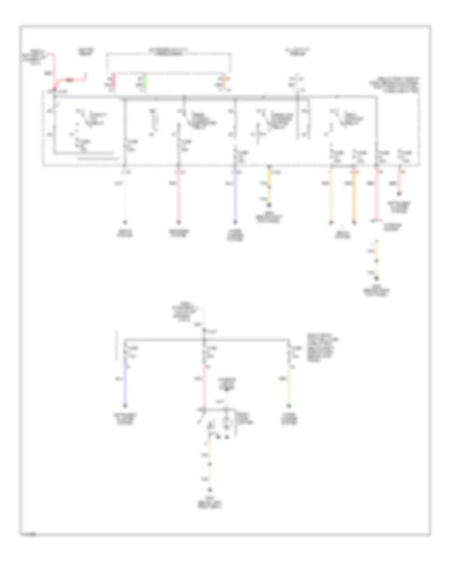
Power Distribution Wiring Diagram (4 of 4) for Mercedes-Benz ML320 2000
List of elements for Power Distribution Wiring Diagram (4 of 4) for Mercedes-Benz ML320 2000:
- (below right side of dash, behind kick panel) right front footwell fuse & relay box
- 87a
- A8 c3
- All activity module
- C4 a12
- Circuit relay
- Defogger system
- Extended activity module (eam)
- From battery a (diagram 1 of 4)
- From starter switch (diagram 2 of 4)
- Front cigar lighter
- Fuse 15a
- Fuse 20a
- Fuse 25a
- Fuse 30a
- Fuse 7.5a
- Fuse 70a
- G203 (behind right kick panel)
- G300 (below left front seat)
- Headlamp cleaning system relay
- Heater relay
- Instrument cluster system
- Interior lights system
- Interior socket
- Pnk
- Rear window defroster relay
- Red
- Right front footwell fuse & relay box (below right side of dash, behind kick panel)
- Seat comfort relay
- Seats system
- Tan
- Wiper/ washer system
- X12/6
- X12/7
- X12/9