POWER DISTRIBUTION
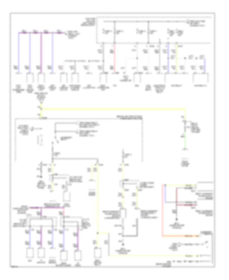
Power Distribution Wiring Diagram (1 of 4) for Subaru Tribeca Limited 2008

List of elements for Power Distribution Wiring Diagram (1 of 4) for Subaru Tribeca Limited 2008:
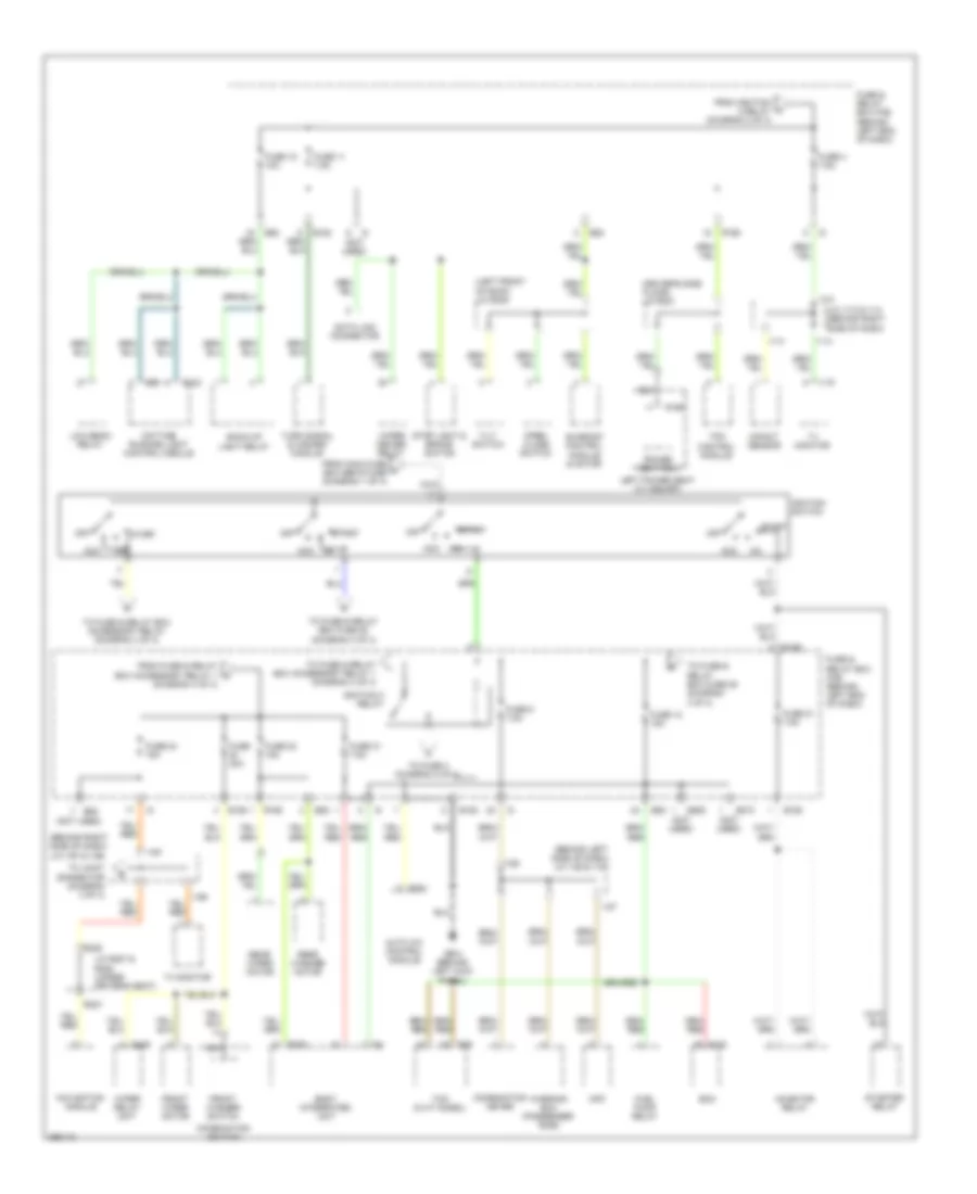
Power Distribution Wiring Diagram (2 of 4) for Subaru Tribeca Limited 2008
List of elements for Power Distribution Wiring Diagram (2 of 4) for Subaru Tribeca Limited 2008:
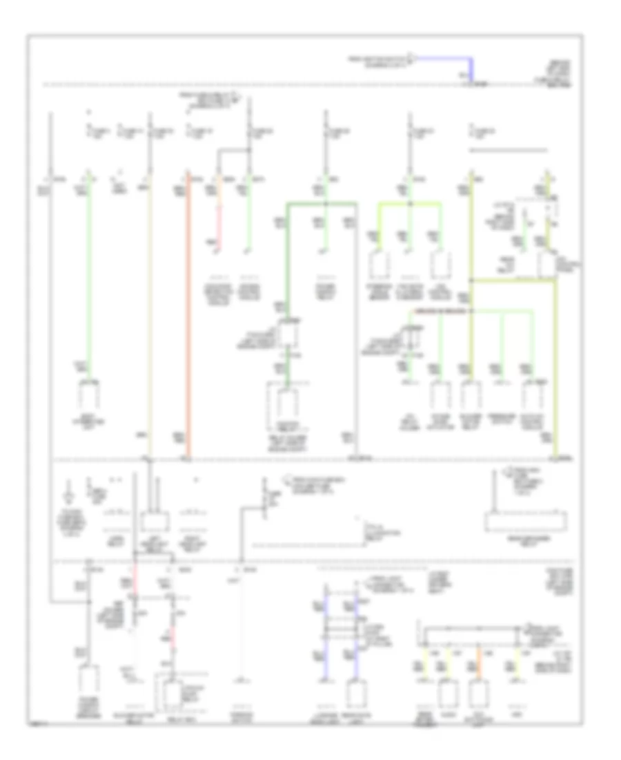
Power Distribution Wiring Diagram (3 of 4) for Subaru Tribeca Limited 2008
List of elements for Power Distribution Wiring Diagram (3 of 4) for Subaru Tribeca Limited 2008:
Power Distribution Wiring Diagram (4 of 4) for Subaru Tribeca Limited 2008
List of elements for Power Distribution Wiring Diagram (4 of 4) for Subaru Tribeca Limited 2008: